Fuel Nozzle of Gas Turbine Combustor and Manufacturing Method Thereof, and Gas Turbine Combustor

a technology of gas turbine combustor and fuel nozzle, which is applied in the direction of manufacturing tools, machines/engines, lighting and heating apparatus, etc., can solve the problem of high probability of backfire in which flames enter an unburned side, and achieve the effect of improving mechanical strength and reliability of the fuel nozzl

Active Publication Date: 2021-06-03
MITSUBISHI HEAVY IND LTD
View PDF0 Cites 0 Cited by
  • Summary
  • Abstract
  • Description
  • Claims
  • Application Information

AI Technical Summary

Benefits of technology

[0013]In one aspect, the present invention considerably improves mechanical strength and reliability of a fuel nozzle for use in, for example, a multi-hole coaxial jet burner and enables healthy operation of a gas turbine combustor including the fuel nozzle over an extended period of time.
[0014]Problems, configurations, and effects of the invention other than those mentioned above will become apparent from the following descriptions of the embodiments of the invention.

Problems solved by technology

The premixed combustion, however, involves a higher likelihood of a backfire in which flames enter an unburned side of a fuel supply portion as a flame temperature increases.

Method used


Image

  • Fuel Nozzle of Gas Turbine Combustor and Manufacturing Method Thereof, and Gas Turbine Combustor
  • Fuel Nozzle of Gas Turbine Combustor and Manufacturing Method Thereof, and Gas Turbine Combustor
  • Fuel Nozzle of Gas Turbine Combustor and Manufacturing Method Thereof, and Gas Turbine Combustor

Examples


first embodiment

[0035]A gas turbine combustor in the present embodiment will be described below with reference to FIGS. 9A and 9B. FIG. 9A is a cross-sectional view showing a structure of main parts of the gas turbine combustor. FIG. 9B is a view on arrow A-A′ in FIG. 9A. The following describes an embodiment in which the present invention is applied to a multi-hole coaxial jet burner. It is noted that FIGS. 9A and 9B are schematic drawings and the number of air holes 55 differs between FIG. 9A and FIG. 9B.

[0036]A burner 53 includes a fuel distributor (end flange) 57, a plurality of fuel nozzles 56, a combustor liner 3, and an air hole plate 54. Specifically, the end flange 57 distributes fuel 41. The fuel nozzles 56 inject the fuel 41. The air hole plate 54 has a disc shape and is disposed at an upstream side end portion of the fuel liner 3. The air hole plate 54 has a plurality of air holes 55 that face a downstream side of the fuel nozzles 56 and through which combustion air 12 passes. A mixture...

second embodiment

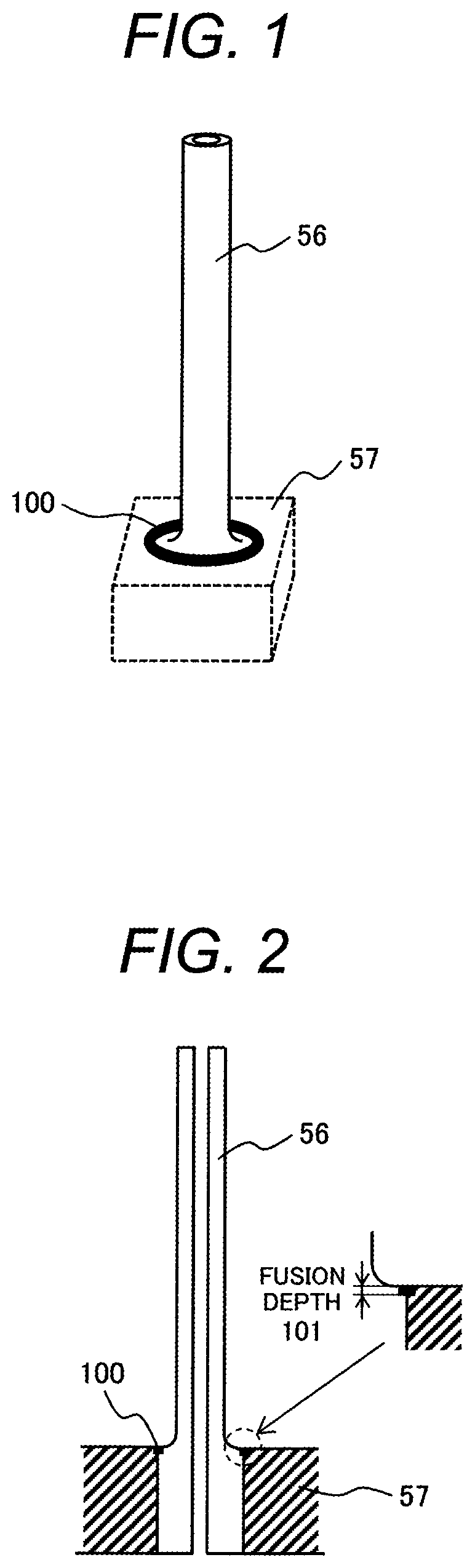
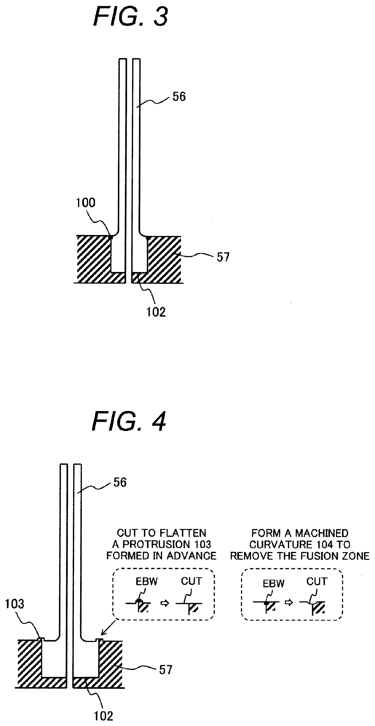
[0050]A fuel nozzle structure in a second embodiment will be described with reference to FIG. 4. FIG. 4 shows a cross-sectional structure of a fuel nozzle 56 and an end flange 57 according to the present embodiment. In the present embodiment, a protrusion 103 is formed in advance at portions of a nozzle root portion and the end flange to which electron beam welding is applied and the protrusion 103 is flattened after the hot isostatic pressing (HIP) process.

[0051]Cutting to remove a fusion zone produced by the electron beam welding (electron beam welding (EBW)) flattens the end flange 57. This allows an undeposited portion that can occur at a bonding end portion to be readily identified and improves inspection performance when the burner including the fuel nozzle 56 is operated for a long time.

[0052]Additionally, the foregoing improves mechanical strength with respect to vibration stress occurring from combustion vibration and to thermal distortion acting on the end flange 57, to th...

third embodiment

[0053]A fuel nozzle structure and a manufacturing method thereof in a third embodiment will be described with reference to FIGS. 8A to 8F. FIG. 8A outlines a manufacturing process in the present embodiment. FIGS. 8B to 8F show more detailed manufacturing steps. The left drawing of FIG. 8A shows a condition corresponding to FIG. 8D and the right drawing of FIG. 8A shows a condition corresponding to FIG. 8F. Each of FIGS. 8A to 8F shows only an area near a root of a fuel nozzle 56 and omits showing a shape of a leading end portion thereof.

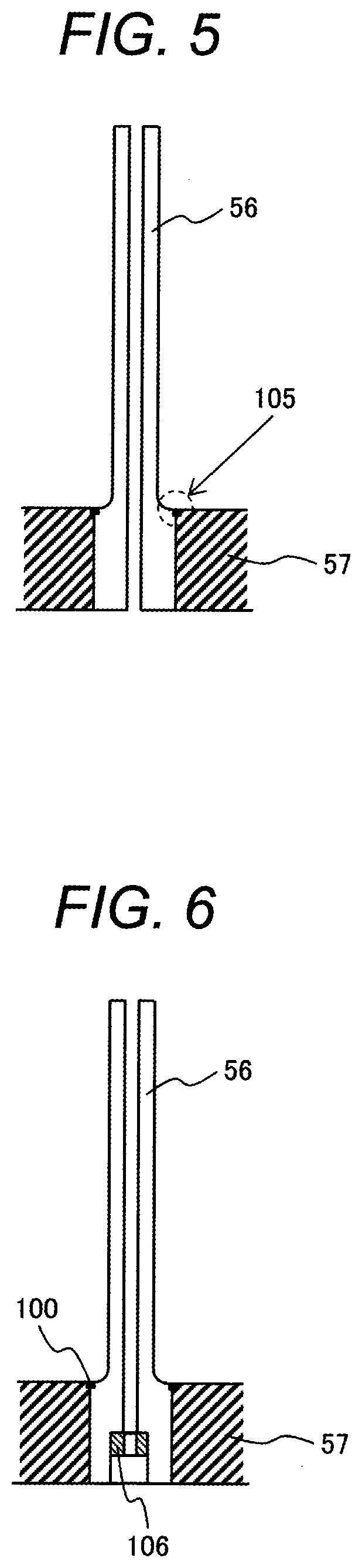
[0054]In the manufacturing method for the fuel nozzle in the present embodiment, the fuel nozzle 56 is inserted into a hole provided in an end flange 57 and a bottom plate 107 is disposed on the side of a back surface of the end flange 57. Electron beam welding is performed on each of a bond portion between the fuel nozzle 56 and the end flange 57 and a bond portion between the end flange 57 and the bottom plate 107 to thereby form an electron beam w...


PUM

PropertyMeasurementUnit
depthaaaaaaaaaa
diameteraaaaaaaaaa
hole diameteraaaaaaaaaa

Abstract

[Problem]To provide a fuel nozzle for a gas turbine combustor, offering favorable durability and strength reliability.[Solving Means]A method for manufacturing a fuel nozzle for a gas turbine combustor, the method comprising: (a) fitting a fuel nozzle having an internal through hole into a through hole or a recess provided in a base plate; (b) bonding, by a fusion joint or a brazing joint, the fuel nozzle to the base plate in an interface therebetween on a surface of the base plate; and (c) following the step of (b), subjecting the fuel nozzle and the base plate to a pressure bonding process to thereby pressure bond the fuel nozzle and the base plate in the interface therebetween.

Description

CLAIM OF PRIORITY[0001]The present application is a divisional of U.S. patent application Ser. No. 15 / 606,023, filed on May 26, 2017, which claims priority from Japanese Patent application serial no. 2016-131411, filed on Jul. 1, 2016, the content of which is hereby incorporated by reference into this application.TECHNICAL FIELD[0002]The present invention relates to combustors and gas turbines including the combustors and, more particularly, to a fuel nozzle structure of a gas turbine combustor including a plurality of multi-hole coaxial jet burners.BACKGROUND ART[0003]A need exists from an environmental preservation viewpoint for further reduction in the amount of NOx in exhaust gas of gas turbines. One known combustion method of the gas turbine combustor is premixed combustion that premixes fuel with air before combustion. This can achieve a considerable reduction in the amount of NOx emissions compared with diffusion combustion in which fuel is directly injected into a combustion...

Claims


Application Information

Patent Timeline
Patent Type & Authority Applications(United States)
IPC IPC(8): F23R3/28F01D9/04F02C3/30F23R3/60
CPCF23R3/286F01D9/04F02C3/30F01D9/02F23R3/60F23R2900/00018F23D2213/00F23R3/283B23K15/0046B23P19/02F02C7/22F05D2240/35F23R2900/00017B23K15/00B23K20/00F23R3/28F05D2300/10F05D2300/17F05D2300/171
Inventor WADAYAMA, YOSHIHIDEKUMAGAI, SATOSHIMIURA, KEISUKEKARISHUKU, MITSUHIRODODO, SATOSHI
Owner MITSUBISHI HEAVY IND LTD
Why Eureka
Try Eureka