Hollow glass body and use of a hollow glass body

a technology of hollow glass and hollow glass, which is applied in the field of hollow glass body, can solve the problems of increasing the rejection rate during the production process, reducing the inside diameter at the end and reducing the inside diameter of the hollow glass body. , to achieve the effect of reducing the inside diameter and efficient handling and further processing

Pending Publication Date: 2021-06-24
NIPRO CORP
View PDF0 Cites 0 Cited by
  • Summary
  • Abstract
  • Description
  • Claims
  • Application Information

AI Technical Summary

Benefits of technology

[0006]The problem to be solved by the invention is the provision of an improved hollow glass body for a receptacle. In particular, a problem to be solved by the invention is the provision of a hollow glass body which can be handled more easily by a machine, for example when the hollow glass body is filled and / or closed, wherein the hollow glass body can be separated from a glass tube using laser radiation. In particular, a problem to be solved by the invention is the provision of a hollow glass body which can be produced using manufacturing techniques that have a low reject rate and / or a high reproducibility. In particular, a problem to be solved by the invention is the provision of a hollow glass body which is suitable as a medical or non-medical receptacle, as a component of such a receptacle or as an intermediate product for such a receptacle.
[0043]Hollow glass bodies according to the present invention can be manufactured in an efficient way using laser cutting. Hollow glass bodies according to the present invention can be efficiently handled and further processed by a machine because they have only a slight reduction in the inside diameter at the second end opening.

Problems solved by technology

Conventional hollow glass bodies that have been separated from a glass tube using laser radiation may show an undesirably large reduction in the inside diameter at the end of the hollow glass body at which the hollow glass body is separated, for example by scratching and subsequent laser-assisted heating in order to introduce mechanical stresses.
Such a significant reduction in the inside diameter at an end opening of the hollow glass body can make the further processing by a machine difficult, increase the reject rate during the production process, and reduce reproducibility of the medical receptacles that comprise the hollow glass body or are produced from the hollow glass body.

Method used


Image

  • Hollow glass body and use of a hollow glass body
  • Hollow glass body and use of a hollow glass body
  • Hollow glass body and use of a hollow glass body

Examples


Embodiment Construction

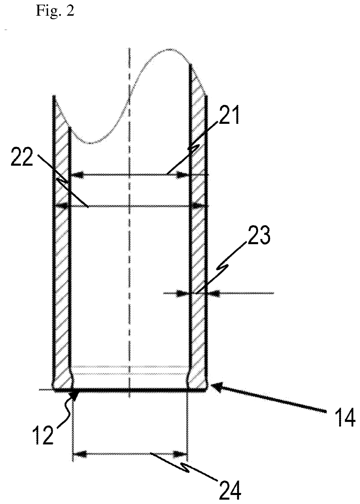
[0058]Hollow glass bodies for medical or non-medical receptacles are described in the following with reference to the Figures. Although some embodiments are described in the context of medical receptacles such as syringes or drug cartridges or in the context of specific production methods, the embodiments are not limited thereto. The hollow glass bodies according to the present invention can also be used for non-medical receptacles.

[0059]A “hollow glass body for a medical receptacle”, as used herein, refers to a hollow glass body that forms a medical receptacle, that is a component of a medical receptacle, or that is an intermediate product for producing a medical receptacle. For example, the hollow glass body may be a syringe or medical cartridge, in particular a drug cartridge, or may be a component of such a medical receptacle. The term “hollow glass body for a non-medical receptacle” can be understood in an analogous manner.

[0060]Hollow glass bodies according to embodiments can ...


PUM

PropertyMeasurementUnit
diameteraaaaaaaaaa
diameteraaaaaaaaaa
diameteraaaaaaaaaa

Abstract

A hollow glass body comprises a cylindrical main body portion having a first inside diameter, and a first end opening and a second end opening on opposite ends of the hollow glass body. The hollow glass body has a second inside diameter at the second end opening. The second inside diameter is smaller than the first inside diameter. A difference between the first inside diameter and the second inside diameter is at most 100 μm.

Description

TECHNICAL FIELD[0001]The invention relates to a hollow glass body. The invention relates in particular to a hollow glass body that may be used for producing a receptacle. The invention relates in particular to a hollow glass body for medical receptacles such as syringes, medical cartridges, or small bottles. The invention relates in particular to such hollow glass bodies that can be separated from a glass tube by using laser radiation during the production.BACKGROUND[0002]Hollow glass bodies can be used as medical receptacles such as syringes or drug cartridges or as non-medical receptacles, can be components of such medical receptacles or non-medical receptacles or can serve as an intermediate product in the production of such medical receptacles or non-medical receptacles.[0003]Laser radiation can be used to reshape hollow glass bodies. DE 10 2010 045 094 A1, DE 10 2012 101 948 A1 and DE 10 2016 114 104 A1 describe exemplary methods and systems for laser-assisted reshaping of a gl...

Claims


Application Information

Patent Timeline
Patent Type & Authority Applications(United States)
IPC IPC(8): A61J1/06A61M5/31B23K26/38B23K26/402C03B33/02C03B33/06
CPCA61J1/065A61M5/3129C03B33/06B23K26/402C03B33/0222B23K26/38B23K26/53B23K26/0622B23K26/0006B23K26/0823B23K26/702B23K37/0426B23K26/0619B23K37/0538Y02P40/57B23K2101/04B23K2103/54A61J1/05A61M5/178B65B3/003
Inventor DROESSLER, MICHAEL
Owner NIPRO CORP
Why Eureka
Try Eureka