Vacuum Processing Apparatus

Active Publication Date: 2021-07-01
ULVAC INC
View PDF0 Cites 0 Cited by
  • Summary
  • Abstract
  • Description
  • Claims
  • Application Information

AI Technical Summary

Benefits of technology

[0012]In this invention, the vacuum processing apparatus preferably further comprises a first recessed part formed on such a surface of the block body as lies opposite to the deposition preventive plate, wherein the heating means is housed in an inside space of the first recessed part. According to this arrangement, since the distance between the block body and the deposition preventive plate can be made shorter, the deposition preventive plate can efficiently be cooled. In this case, the inner surface of the first recessed part is preferably made up of a low-emissivity layer having a lowered emissivity as a result of surface treatment to the parent metal of the b

Problems solved by technology

Should these kinds of ejected gases be taken into the thin film at the time of film forming, deterioration in film quality, for example, will re

Method used


Image

  • Vacuum Processing Apparatus
  • Vacuum Processing Apparatus
  • Vacuum Processing Apparatus

Examples


Embodiment Construction

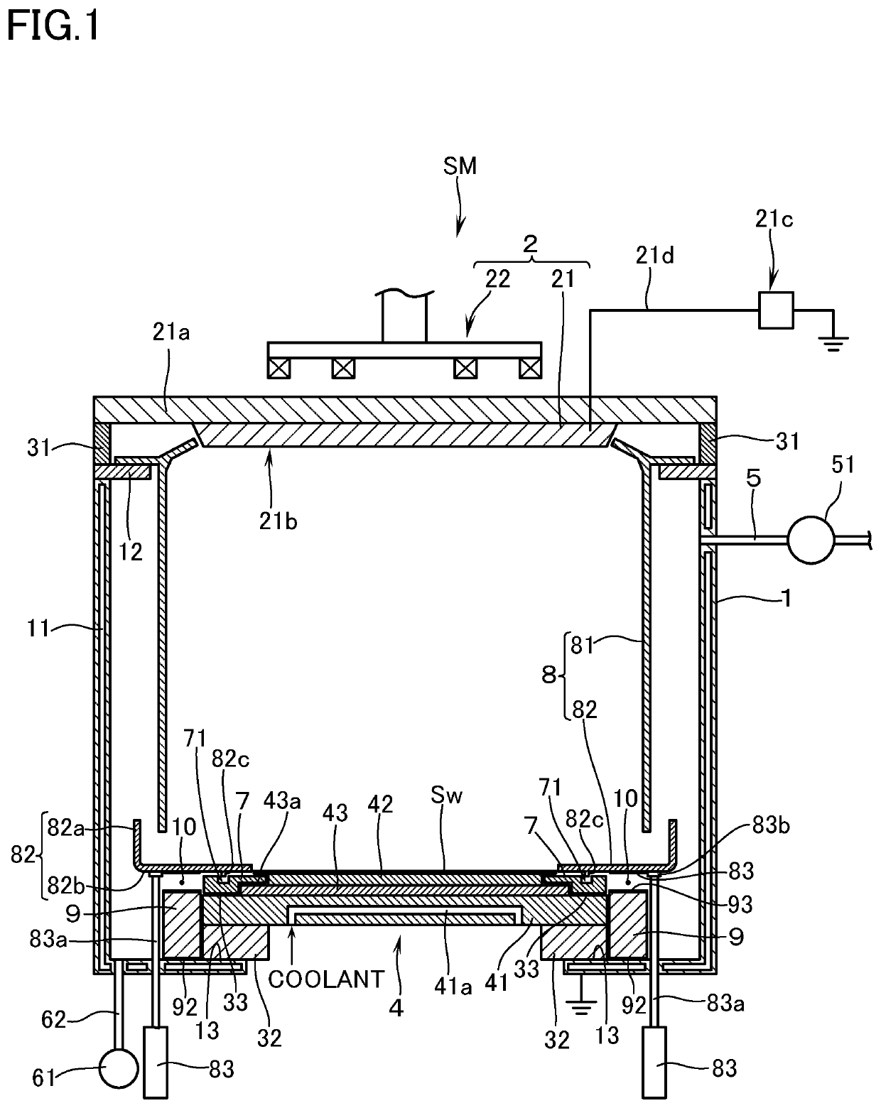
[0019]With reference to the drawings, a description will hereinafter be made of an embodiment of a vacuum processing apparatus based on an example in which, provided that the vacuum processing apparatus is a magnetron type of sputtering apparatus, and that the to-be-processed substrate is a silicon wafer (hereinafter referred to as a “substrate Sw”), a predetermined thin film is formed on a surface of the substrate Sw. In the following description, the terms denoting the direction shall be based on the posture of installation of the sputtering apparatus as the vacuum processing apparatus as shown in FIG. 1.

[0020]With reference to FIG. 1, the mark SM denotes a sputtering apparatus according to this embodiment. The sputtering apparatus SM is provided with a vacuum chamber 1. The side walls and the lower wall of the vacuum chamber 1 are provided with a jacket 11 connected to a circulation unit for a heating medium or a coolant (not illustrated) so that the side wall and the lower wall ...


PUM

PropertyMeasurementUnit
Emissivityaaaaaaaaaa

Abstract

Provided is a vacuum processing apparatus which is capable of performing baking processing of a deposition preventive plate without impairing the function of being capable of cooling the deposition preventive plate disposed inside a vacuum chamber. The vacuum processing apparatus has a vacuum chamber for performing a predetermined vacuum processing on a to-be-processed substrate that is set in position inside the vacuum chamber. A deposition preventive plate is disposed inside the vacuum chamber. Further disposed are: a metallic-made block body vertically disposed on an inner surface of the lower wall of the vacuum chamber so as to lie opposite to a part of the deposition preventive plate with a clearance thereto; a cooling means for cooling the block body; and a heating means disposed between the part of the deposition preventive plate and the block body to heat the deposition preventive plate by heat radiation.

Description

TECHNICAL FIELD[0001]The present invention relates to a vacuum processing apparatus having a vacuum chamber and performs a predetermined vacuum processing on a substrate to be processed (hereinafter referred to as a “to-be-processed substrate”) set in the vacuum chamber.BACKGROUND ART[0002]In a process of manufacturing, e.g., semiconductor devices, there is included a step in which a predetermined vacuum processing such as film forming processing and etching processing is performed on a to-be-processed substrate such as a silicon wafer, and the like. As a vacuum processing apparatus to be used in this kind of vacuum processing, there is known in patent document 1 a sputtering apparatus for performing film forming by a sputtering method. This apparatus has a vacuum chamber which is capable of forming a vacuum atmosphere. In an upper part of the vacuum chamber there is disposed a target for sputtering. In a lower part of the vacuum chamber there is provided a stage on which is set in ...

Claims


Application Information

Patent Timeline
IPC IPC(8): C23C14/35C23C14/54C23C14/34H01J37/32
CPCC23C14/35C23C14/541H01L21/2855H01J37/32724C23C14/3407C23C14/50H01J37/32477H01J37/32522H01J37/32871C23C14/564C23C14/54H01J37/32651
Inventor FUJII, YOSHINORI
Owner ULVAC INC
Why Eureka
Try Eureka