

Method and apparatus for controlling fiber cross-alignment in a nanofiber membrane
- Summary
- Abstract
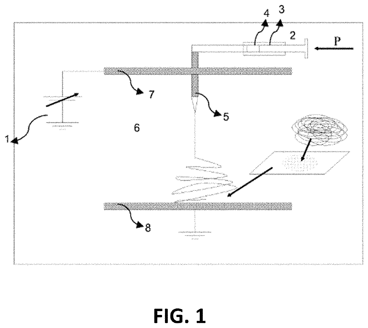
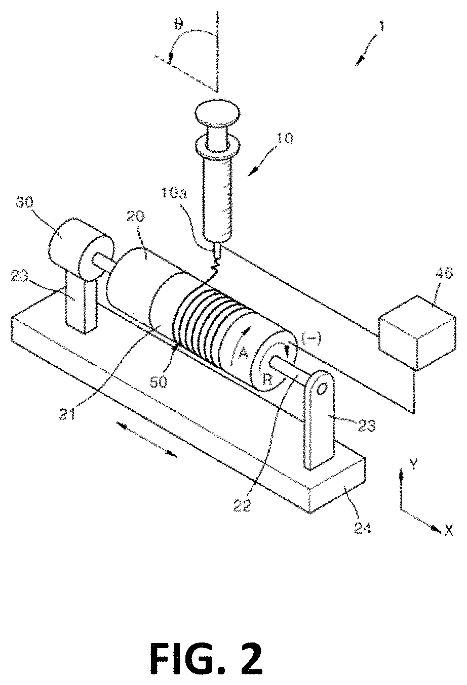
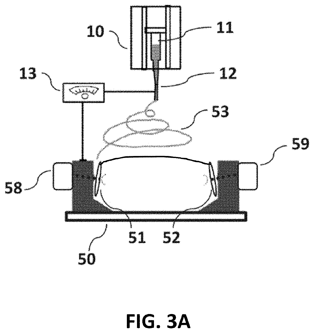
- Description
- Claims
- Application Information
AI Technical Summary
Benefits of technology
Problems solved by technology
Method used
Image

Examples
examples
[0125]The present disclosure can be better understood with reference to the following non-limiting examples.
[0126]Nanofiber scaffolding structures and aligned fibers produced using the apparatus and methods of the present invention have applications in medicine, including at least artificial organ components, tissue engineering, implant material, drug delivery, wound diagnostics, bacterial detection, wound dressing, and medical textile materials. Nanofiber scaffolding structures may be used to fight against viral infection (e.g., HIV-1, SARS-2), and be able to be used as a contraceptive. In wound healing, nanofiber scaffolding structures assemble at the injury site and stay put, drawing the body's own growth factors to the injury site. These growth factors comprise naturally occurring substances such as proteins and steroid hormones capable of stimulating cellular growth, proliferation, healing, and cellular differentiation. Growth factors are important for regulating a variety of c...
PUM
| Property | Measurement | Unit |
|---|---|---|
| Magnetic field | aaaaa | aaaaa |
| Electric charge | aaaaa | aaaaa |
| Antimicrobial properties | aaaaa | aaaaa |
Abstract
Description
Claims
Application Information