Elastic layers with fibers
Pending Publication Date: 2021-07-29
APT ADVANCED POLYMER TECH CORP +1
0 Cites 0 Cited by
AI-Extracted Technical Summary
Problems solved by technology
Sometimes, artificial turf is perceived as being insufficiently “bouncy” if the elasticity of the artificial turf is not sufficient to allow a ball to bounce back quickly.
Moreover, artificial turf is sometimes perceived as insufficiently elastic to effectively protect the joints of the players from injury.
This is because the frequent freeze-thaw cycles damage the stone substrate onto which the elastic layer and/or the sports floor is placed.
Larger cracks and holes are created by water that has managed to penetrate the base layer, because when water freezes to ice, it has a larger volume and may thus burst even concrete or stone over the years.
If a ball hits a spo...
Benefits of technology
[0048]Optionally, the sports floor is glued, nailed, tacked, or otherwise fixed onto the e-layer. This may prevent the sports floor from being moved relative to the e-layer.
[0049]Preferably, the sports floor is applied onto...
Abstract
The invention relates to an elastic layer (202) for use as a support layer of sports floor (302), the elastic layer being made of a mixture of fibers (206), elastic granules (208), and a binder (204).
Application Domain
Ground pavingsDomestic articles
Technology Topic
Polymer chemistryFiber +1
Image
Examples
- Experimental program(1)
Example
[0069]Like-numbered elements in these figures either are equivalent elements or perform the same function. Elements that have been discussed previously will not necessarily be discussed in later figures if the function is equivalent.
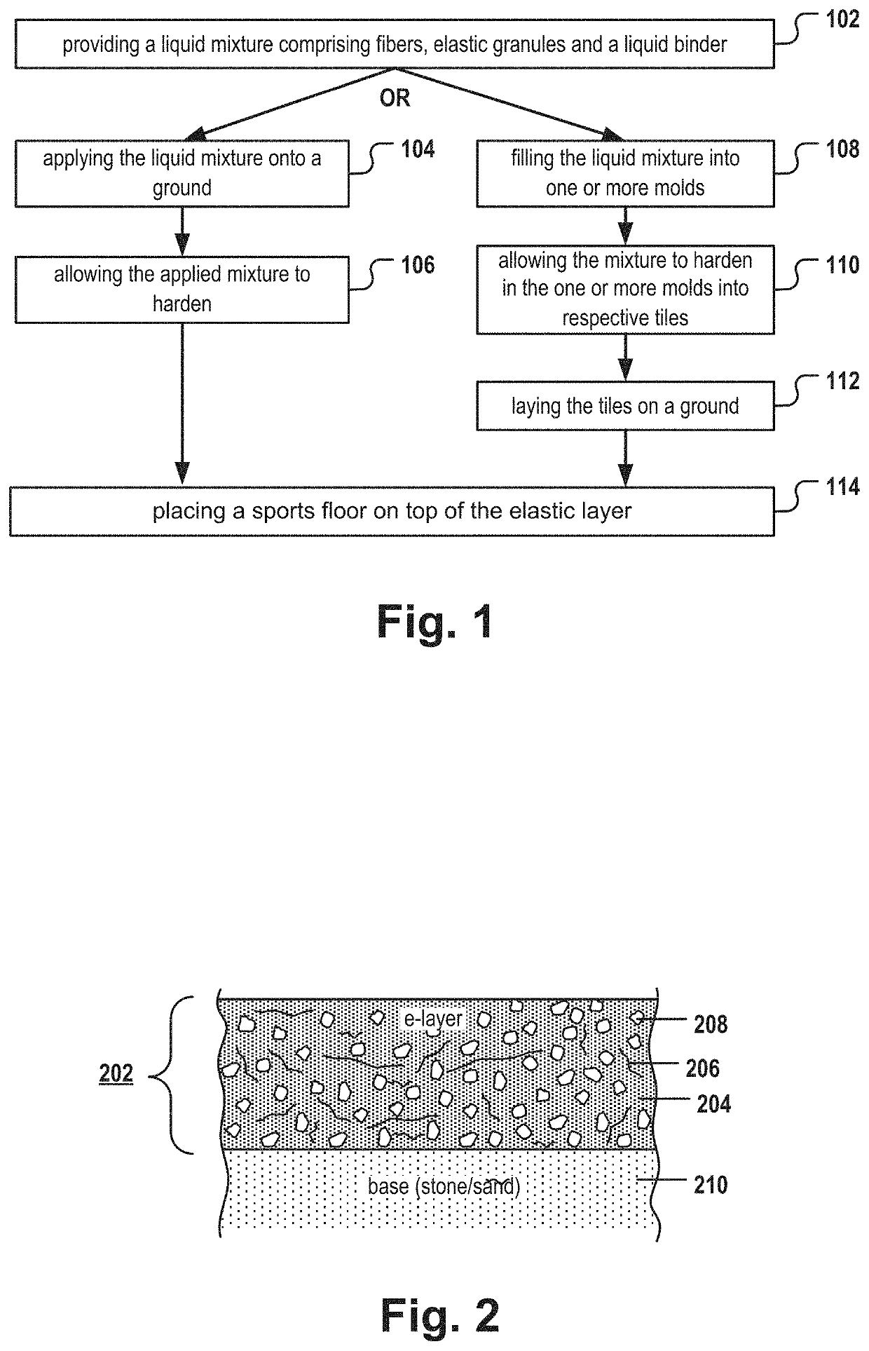
[0070]FIG. 1 is a flow chart of a method of manufacturing an e-layer (202). The e-layer is designed and adapted for use as a support layer of a sports floor, e.g. of an artificial turf (302). The method comprises a step 102 of providing a liquid mixture. The mixture comprises fibers 206, elastic granules 208 and a liquid binder 204. For example, the mixture can be created manually or automatically (e.g., by a stirring device). The mixture is mixed until the granules, the fibers, and the binder are homogeneously mixed. Depending on the particular composition of the mixture, this may take 2-20 minutes. The greater the amount of elastic granules, the higher the elasticity of the e-layer. The greater the amount of fibers, the higher the tensile strength of the e-layer.
[0071]Typically, the liquid mixture is a highly viscous mixture.
[0072]According to embodiments, 0.5% to 40%, more preferentially 5% to 20%, in particular 5% to 10% by weight of the mixture consist of the fibers.
[0073]According to embodiments, the weight ration of the binder to the total weight of the elastic granules and the fibers combined is in the range of 5:100 to 15:100, more preferably 8:100 to 10:100. For instance, 8 kg of the binder can be mixed with 100 kg of a fiber-granule mixture. In one example, about 25% of the fiber-granule mixture consist of the fibers and about 75% of the fiber-granule mixture consist of the elastic granules.
[0074]According to some embodiments, the artificial turf fibers are made of polyethylene that has been obtained from an old, worn-out artificial turf. The binder can be a polyurethane binder. The elastic granules can be SBR or EPDM rubber granules or other types of granular, elastic material. The SBR rubber granules can be obtained, for example, from shredded used tires which may optionally be PU coated.
[0075]Next, in step 104, the liquid mixture is applied onto a base layer 210 (e.g., a concrete layer at the use site where the sports floor is to be installed). The liquid mixture is applied until the desired height is obtained. The height of the e-layer depends on the intended use. Typically, the height of the e-layer is in the range of 8 mm-40 mm. Next, in step 106, the liquid mixture is allowed to solidify. For example, the PU binder can be a liquid one-component (1C) or two-component (2C) PU reaction mixture that solidifies by reacting the PU reaction mixture into a solid PU mass that constitutes the e-layer.
[0076]Alternatively, the liquid mixture is generated at a manufacturing plant and is poured in step 108 into one or more molds. The mold can have the shape of a single, long tile or “lane” for generating a molded article that can be rolled up after solidification. Alternatively, one or more molds can have a tile shape that is similar to a square or to a rectangle with sides of more similar length. The molds are adapted for fabricating e-layer tiles. For example, a square-shaped mold can have the dimensions of 100 cm×100 cm×3 cm. Alternatively, the tiles could have the shape of a rectangle wherein one side is 1.1 to 10 times longer than the other side.
[0077]In step 110, the liquid mixture is allowed to solidify within the molds into tiles 502.
[0078]Finally, the solidified e-layer tiles are removed from the molds, transported to the use site, and laid in step 112 on a base layer 210. In a further step 114, a sports floor, here the artificial turf layer 302, is applied on top of the e-layer. The sports floor can simply be put on top of the e-layer or can be firmly attached to the e-layer by applying an adhesive layer on top of the e-layer and then applying the sports floor onto the adhesive layer. In some embodiments, the e-layer is punched before or after the sports floor layer is applied in order to generate drainage holes for preventing the formation of puddles.
[0079]FIG. 2 is a schematic, cross-sectional view of an e-layer 202 that was applied on top of a base layer 210. The e-layer comprises fibers 206 of varying lengths and elastic granules 208. The granules and the fibers are embedded in a binder 204. The diameter of the granules can be, for example, in the range of 1 mm-5 mm. FIG. 2 is for illustration only, and the share of the granules 208 and the fibers 206 in the total volume of the e-layer may not reflect exactly the real situation.
[0080]FIG. 3 is a schematic, cross-sectional view of a pavement structure 300 comprising an e-layer 202 as described in greater detail for example with reference to FIG. 2, and a sports floor layer 302.
[0081]FIG. 4 is a schematic, cross-sectional view of a pavement structure comprising an e-layer 202 and a sports floor layer 302 in the form of an artificial turf layer. The artificial turf layer 302 comprises a plurality of artificial turf fibers 402 which have been incorporated into a carrier layer 404. For example, the fibers 402 can be polymer fibers, whereby the polymer is polyethylene, polyamide, nylon, polypropylene, or a mixture thereof. The fibers can be incorporated into the carrier (e.g., by tufting, knitting, or weaving). The carrier can be a synthetic fiber mesh or a plant fiber mesh or any other sheet-like structure allowing an incorporation of the artificial turf fibers. Optionally, the artificial turf 302 can comprise a backing 406—e.g., a PU backing layer or a latex layer that incorporates short, U-shaped fiber portions and thereby firmly fixes the fibers in the carrier. In addition, the artificial turf may optionally further comprise an infill layer 408. The infill material can consist of sand and/or elastic granules (e.g., rubber granules or cork granules). The infill granules can be coated. Using an e-layer below the artificial turf may be beneficial as this may allow achieving a desired degree of elasticity without the need to add elastic infill. Alternatively, a comparatively thin infill layer 408 having a height of less than 2 cm, preferably less than 1 cm, may be sufficient to provide a highly elastic artificial turf ground, because the elasticity is already provided by the e-layer. According to some embodiments, the artificial turf 302 does not have a backing or has only a very thin backing having a thickness of less than 2 mm. The backing is commonly applied on the back side of the carrier for fixing the fibers in the carrier and for increasing the elasticity of the artificial turf. According to embodiments of the invention, a sufficient degree of elasticity is already provided by the e-layer, so the thickness of the backing may be reduced or the backing may even be absent. This may reduce the costs of manufacturing the artificial turf layer.
[0082]FIG. 5 illustrates the installation of multiple e-layer tiles 502 on a base layer at a use site, thereby providing an elastic support layer 202 for artificial turf. After the installation of the e-layer is completed, the artificial turf is installed on top of the e-layer.
LIST OF REFERENCE NUMERALS
[0083]100-114 steps
[0084]202 elastic layer
[0085]204 binder
[0086]206 fiber
[0087]208 elastic granule
[0088]210 base layer
[0089]300 pavement structure
[0090]302 sports floor (artificial turf)
[0091]402 artificial turf fibers
[0092]404 carrier
[0093]406 backing
[0094]408 infill layer
[0095]502 e-layer tile
PUM
Property | Measurement | Unit |
Fraction | 0.1 | fraction |
Fraction | 0.6 | fraction |
Length | 0.01 | m |
Description & Claims & Application Information
We can also present the details of the Description, Claims and Application information to help users get a comprehensive understanding of the technical details of the patent, such as background art, summary of invention, brief description of drawings, description of embodiments, and other original content. On the other hand, users can also determine the specific scope of protection of the technology through the list of claims; as well as understand the changes in the life cycle of the technology with the presentation of the patent timeline. Login to view more.