
Apparatus for treating excess intraocular fluid having an elastic membrane

a technology of intraocular fluid and apparatus, applied in the field of apparatus for draining excess intraocular fluid, can solve the problems of optic nerve, total blindness, loss of vision,

Pending Publication Date: 2021-09-09
ECOLE POLYTECHNIQUE FEDERALE DE LAUSANNE (EPFL)
View PDF4 Cites 1 Cited by
  • Summary
  • Abstract
  • Description
  • Claims
  • Application Information

AI Technical Summary

Benefits of technology

The patent describes a device for treating damage to the eye, such as glaucoma. The device has a housing shell that is placed on top of the eye and is made of a material that is safe for the body. The housing shell has a curved shape to match the shape of the eye. To protect the eye, a protective patch is placed on top of the housing shell. The device also has a structure that allows fluid to flow through it. This structure helps to control the flow of fluid and can help to reduce the risk of damage to the eye during treatment.

Problems solved by technology

Left untreated, this disease typically causes damage to the optic nerve, with consequent loss of vision, initially peripheral, but progressively leading to total blindness.
Unfortunately, glaucoma is often asymptomatic until late in the progress of the disease.
Such medications do not cure glaucoma, and must be continue to be taken to maintain intraocular pressures within accepted limits.
In certain cases, such treatment may fail and other surgical treatments are employed, such as filter procedures or placement of a glaucoma drainage device.
One drawback of devices such as those described in the Molteno patent is that the drainage flow depends on IOP and on the fixed hydrodynamic resistance of the shunt.
In many cases, however, the hydrodynamic resistance of the shunt may not be sufficient to reduce high IOP when the resistance to flow is too high, or may lead to over-drainage if the resistance is low.
For example, a common problem, which arises shortly after implantation, is hypotony, which occurs when IOP drops below acceptable physiological levels (i.e., IOP<6 mmHg).
Hypotony usually takes place the first few days to weeks following the implantation of a glaucoma drainage device, and is a combined result of a low fluidic resistance of both the implant and the distal outflow paths.
Hypotony may lead to a number of undesirable effects and complications, such as hypotensive maculopathy, cataract formation and optic nerve edema.
Another problem, also related to the fixed fluid resistance of previously known implants, is fibrosis, which appears progressively at long term and which, depending on its extent and severity, may raise the effective fluidic resistance of the implant, thereby raising the IOP to different, often non-physiological, levels.
Unfortunately, the operational characteristics of the system depend on the properties of the membrane, which cannot be changed easily once the device is implanted.
Also, the valve of Ahmed does not provide a true opening pressure to accurately control post-operation IOP.
However, one skilled and experienced in the field of medical implants, especially in ophthalmology, would understand that such a system with a constant external pressure chamber would be very impractical, if not impossible, to make.
Unfortunately, significant deformation of the semi-permeable membrane makes it difficult to predict the osmotic pressure within the pressurized enclosure.
Other previously-known glaucoma treatment systems include significantly greater complexity to address the drawbacks of the simpler shunt systems described above.
In addition, the regulating mechanism is complex, including many rotating parts and gears, and this complexity poses a risk of malfunction.

Method used


Image

  • Apparatus for treating excess intraocular fluid having an elastic membrane
  • Apparatus for treating excess intraocular fluid having an elastic membrane
  • Apparatus for treating excess intraocular fluid having an elastic membrane

Examples


Embodiment Construction

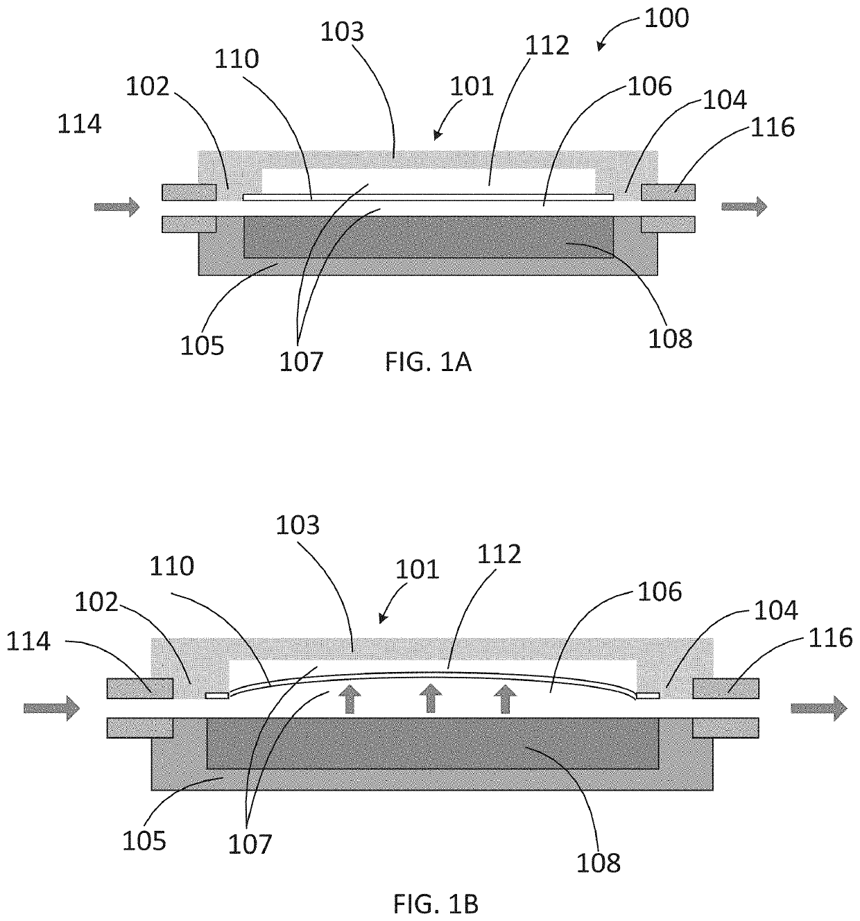
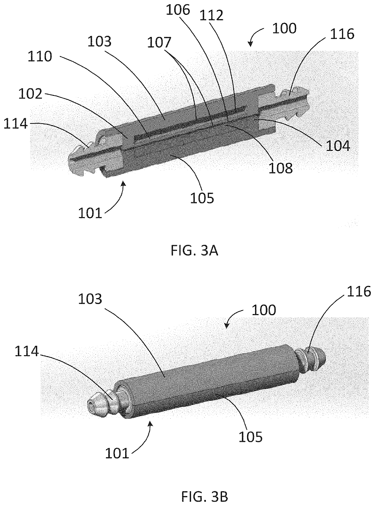
lass="d_n">[0041]In accordance with the principles of the present invention, an implantable device is provided for treating excessive intraocular pressure within an eye. In a preferred embodiment, the implantable device includes a cavity and an elastic membrane disposed within the cavity, thereby creating a fluidic passageway through the device. The elastic membrane is self-regulating to control the flow of aqueous humor from an anterior chamber of the eye, through the passageway, to a sink outside the eye (e.g., a bleb formed under a scleral flap or the orbital fat space of the eye). In accordance with one aspect of the present invention, the implantable device includes an area of local constriction disposed within the cavity to reduce the area of the fluidic passageway to increase fluidic resistance of the flow of fluid through the passageway. In an alternative embodiment, the implantable device includes a circular-shaped passageway such that the elastic membrane is positioned aro...


PUM


Abstract

Apparatus and methods are provided for treating diseases that produce elevated intraocular pressures, such as glaucoma, wherein the device includes a housing shell defining a cavity between a first end and a second end of the housing shell, and an elastic membrane disposed within the cavity to divide the cavity into a fluidic channel that permits a flow of fluid from the first end to the second end and a sealed cavity. The elastic membrane deforms to change the volume of the sealed cavity responsive to pressure fluctuations between the first and second ends, thereby varying the fluidic resistance of the flow of fluid through the fluidic channel.

Description

CROSS-REFERENCE TO RELATED APPLICATIONS[0001]This application claims the benefit of priority of U.S. Provisional Application No. 62 / 986,604, filed Mar. 6, 2020, the entire contents of which are incorporated herein by reference. This application is also related to PCT International Application No. PCT / IB2019 / 057509, filed Sep. 6, 2019, published as WO 2020 / 049508 A1 on Mar. 12, 2020, which claims the benefit of priority of U.S. Provisional Application No. 62 / 728,022, filed Sep. 6, 2019, the entire contents of each of which are incorporated herein by reference. This application is further related to U.S. patent application Ser. No. 15 / 612,988, filed Jun. 2, 2017, now U.S. Pat. No. 10,596,035, which claims the benefit of priority of U.S. Provisional Application No. 62 / 346,456, filed Jun. 6, 2016, the entire contents of each of which are incorporated herein by reference.FIELD OF INVENTION[0002]This application relates to an apparatus for draining excess intraocular fluid to relieve intr...

Claims


Application Information

Patent Timeline
Patent Type & Authority Applications(United States)
IPC IPC(8): A61F9/007
CPCA61F9/00781
Inventor STERGIOPULOS, NIKOLAOSSTERGIOPULOS, CONSTANTINOS
Owner ECOLE POLYTECHNIQUE FEDERALE DE LAUSANNE (EPFL)
Learn More