Water injection

a gas turbine engine and water injection technology, applied in the direction of efficient propulsion technologies, machines/engines, lighting and heating apparatus, etc., can solve problems such as unwanted warming

Active Publication Date: 2021-09-09
ROLLS ROYCE PLC
View PDF0 Cites 1 Cited by
  • Summary
  • Abstract
  • Description
  • Claims
  • Application Information

AI Technical Summary

Problems solved by technology

During both day and night, aviation-induced cloudiness also intercepts outgoing infrared radiation, leading to unwanted warming.

Method used


Image

  • Water injection
  • Water injection
  • Water injection

Examples


Embodiment Construction

FIG. 1

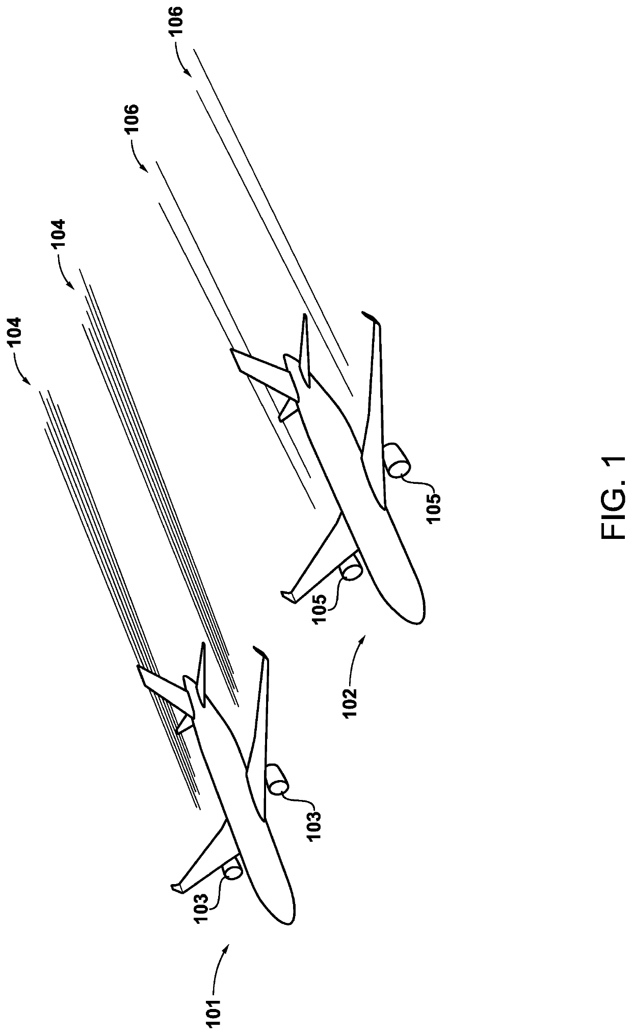
[0030]Two aircraft 101 and 102 are illustrated in FIG. 1 in formation at substantially the same flight level and in substantially the same atmospheric conditions.

[0031]Aircraft 101 comprises two engines 103 which, due to their configuration and operating point, are forming contrails 104. Aircraft 102 comprises two engines 105 which are configured in accordance with the present disclosure, and are thus forming contrails 106 having a lower optical depth than contrails 104. As will be described herein, the engines 105 include functionality so as to allow the optical depth of any contrails they produce to be modified.

[0032]As used herein, optical depth is a measure of how much electromagnetic radiation, optionally in certain wavelength ranges, is prevented from travelling through a region. In the case of a contrail or ice cloud, optical depth is influenced primarily by the ice particle number density, effective ice particle radius, and the physical thickness of the cloud. Since mo...


PUM


Abstract

A gas turbine engine for an aircraft. The gas turbine comprises a combustor, a fuel injection system connected with a source of fuel and configured to inject fuel into the combustor, a water injection system connected with a source of water and which is configured to inject water into the combustor, and a control system. The control system is configured to identify an atmospheric condition; determine a water-fuel ratio for injection into the combustor of the gas turbine engine in response to the atmospheric condition; and control injection of fuel and water by the fuel injection system and the water injection system according to said water-fuel ratio to control an soot emissions caused by combustion of fuel therein.

Description

CROSS REFERENCE TO RELATED APPLICATIONS[0001]This application claims priority from United Kingdom Patent Application Numbers 2003094.6 and 2003095.3, both filed Mar. 4, 2020, the whole contents of which are incorporated herein by reference in their entirety.BACKGROUNDTechnical Field[0002]This disclosure concerns aircraft gas turbine engines with water injection systems, and methods of operation thereof.Description of the Related Art[0003]Combustion of hydrocarbon fuels in aero engine combustion systems produces a hot exhaust stream composed primarily of nitrogen, oxygen, carbon dioxide and water vapour. In addition to these major components, a quantity of soot is also produced in locally-rich flame zones, along with thermal nitrogen oxides and sulphur oxides. Unburnt hydrocarbons and carbon monoxide may also be emitted in very low concentrations, together with trace quantities of other particulates.[0004]The emission of a warm, moist exhaust plume into the cold ambient air found at ...

Claims


Application Information

Patent Timeline
Patent Type & Authority Applications(United States)
IPC IPC(8): F02C9/40
CPCF02C9/40F05D2270/804F05D2270/08F05D2220/323F02C7/228F02C9/263F02C9/28F05D2270/081F05D2270/331F02C3/30Y02T50/60F23R3/346
Inventor MADDEN, CHRISTOPHER P.SWANN, PETER
Owner ROLLS ROYCE PLC
Why Eureka
Try Eureka