Pressure testing method and pressure tester

Pending Publication Date: 2021-09-30
TOYOTA JIDOSHA KK
View PDF0 Cites 1 Cited by
  • Summary
  • Abstract
  • Description
  • Claims
  • Application Information

AI Technical Summary

Benefits of technology

The present patent provides a method and device for accurately testing whether a high-pressure tank is damaged. This helps to prevent accidents and improve safety.

Problems solved by technology

Such a method is unable to accurately determine whether the tank is deteriorated.
The pressure resistance test conducted by increasing the internal pressure of the high-pressure tank causes cracks in the fiber-reinforced resin layer, and the cracks trigger AE waves.
When the cumulative number of the AE waveforms reaches or exceeds a given value (threshold), the high-pressure tank is more likely to be deteriorated.

Method used


Image

  • Pressure testing method and pressure tester
  • Pressure testing method and pressure tester
  • Pressure testing method and pressure tester

Examples


first embodiment

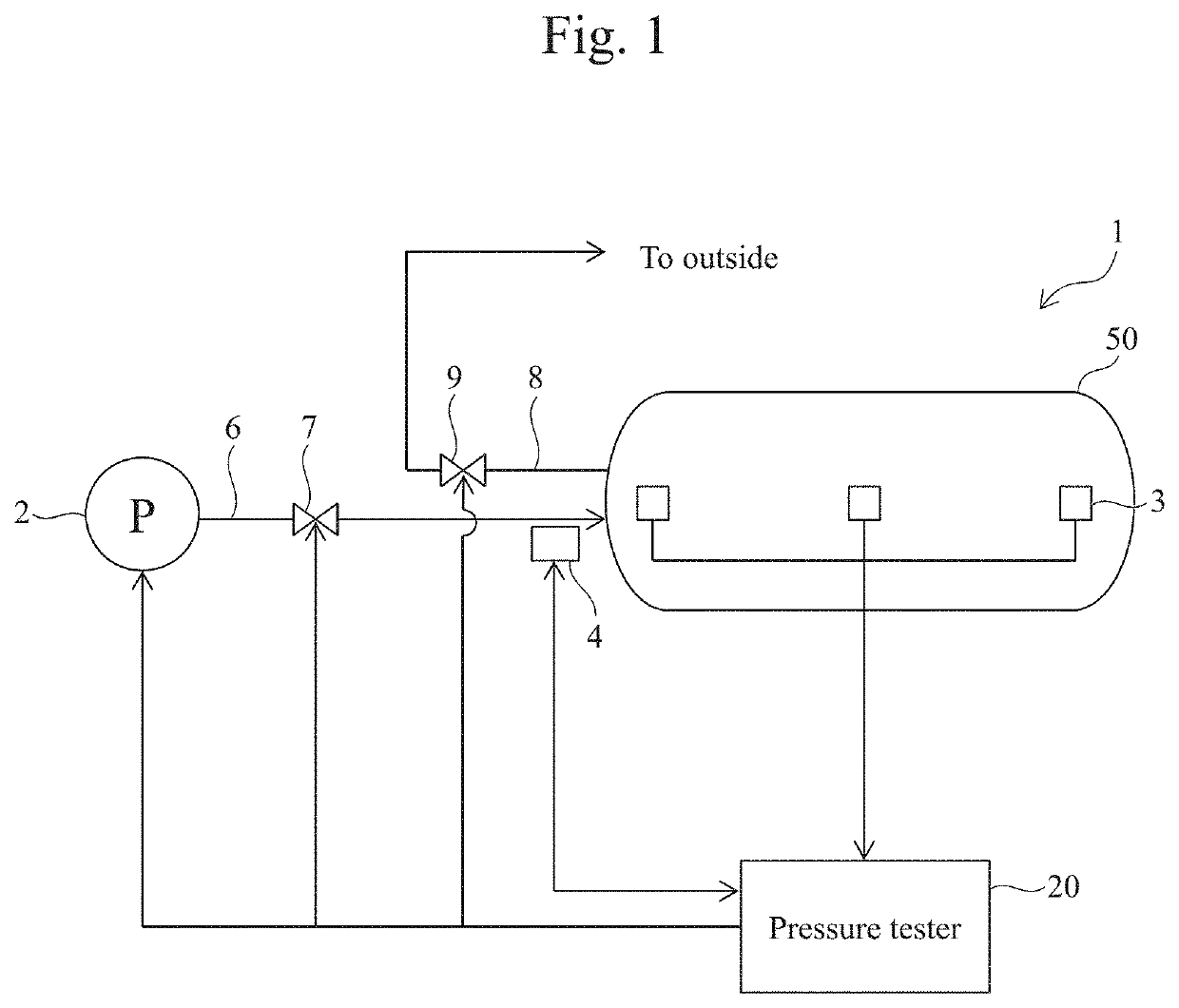
[0031]Referring to the drawings, the following describes a test system 1 including a pressure tester 20 according to a first embodiment of the present disclosure. FIG. 1 is a schematic view showing the overall configuration of the test system 1 including the pressure tester 20 according to the first embodiment of the present disclosure.

[0032]As shown in FIG. 1, the test system 1 tests a high-pressure tank 50. The high-pressure tank 50 is, for example, a tank to be mounted on a fuel cell vehicle and filled with a high-pressure hydrogen gas. The gas that can be filled in the high-pressure tank 50 is not limited to a hydrogen gas. The high-pressure tank 50 undergoes a pressure resistance test after the manufacturing (before shipping). The high-pressure tank 50 that has passed the pressure resistance test is mounted on a vehicle. The test system 1 tests the high-pressure tank 50 either being mounted on or temporarily removed from a vehicle for vehicle inspection or the like.

[0033]The te...

second embodiment

[0076]The second embodiment describes a case where, unlike the first embodiment, the plurality of AE waveforms extracted by the extractor 121 is classified into the first waveforms derived from macrocracks and the second waveforms derived from microcracks smaller than the macrocracks.

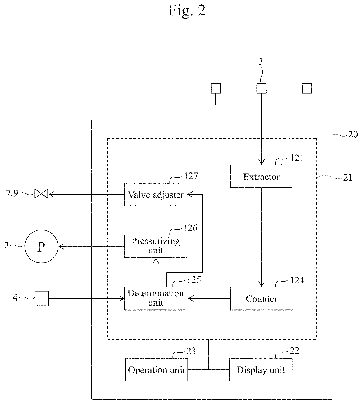
[0077]In the present embodiment, as shown in FIG. 7, the controller 21 of the pressure tester 20 further includes a converter 122 and classifier 123, as software, in addition to the extractor 121, counter 124, determination unit 125, pressurizing unit 126, and valve adjuster 127. In the present embodiment, the extractor 121, counter 124, determination unit 125, converter 122, and classifier 123 constitute the “calculation device” of the present disclosure.

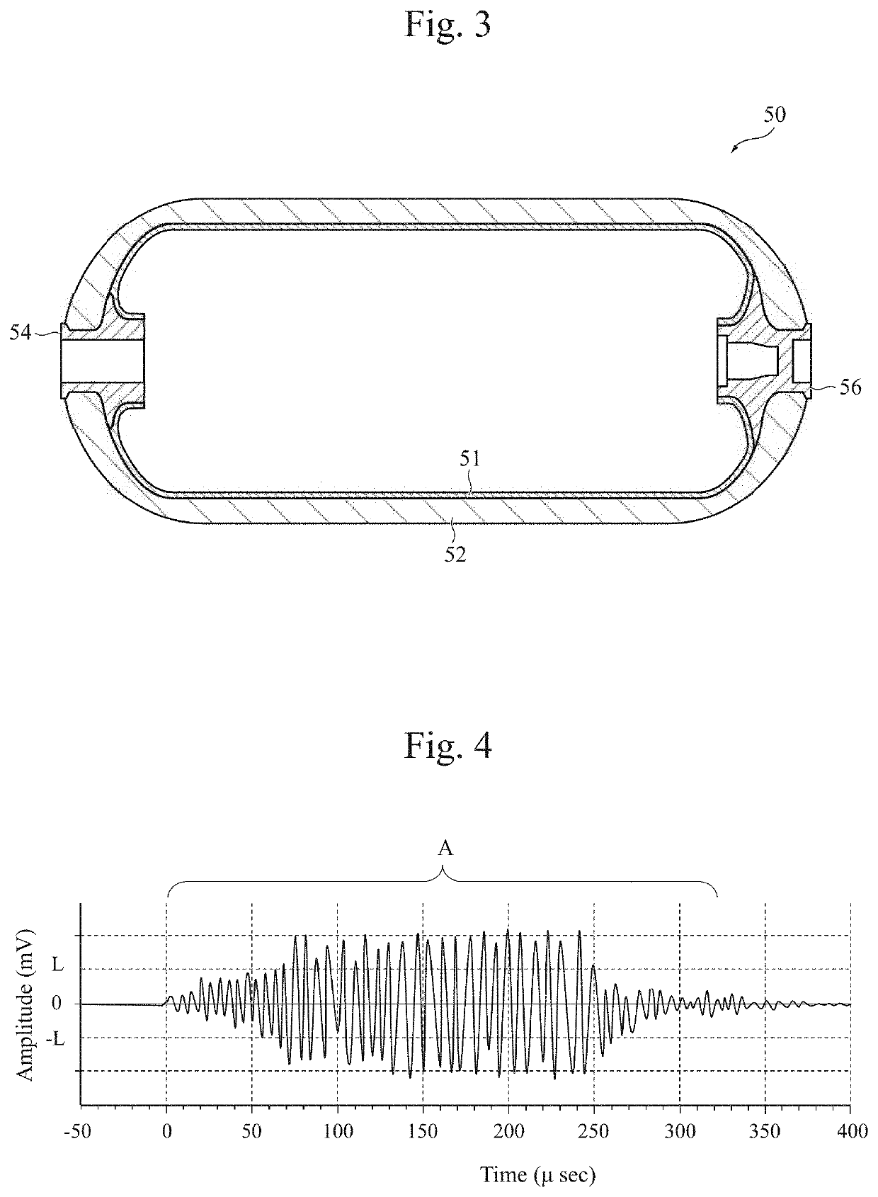
[0078]The extractor 121 sequentially extracts a plurality of AE waveforms from the output waveforms of the AE sensor 3 and outputs them to the converter 122.

[0079]When the AE waveforms derived from the plurality of AEs are connected to be output as one...


PUM

PropertyMeasurementUnit
Timeaaaaaaaaaa
Lengthaaaaaaaaaa
Lengthaaaaaaaaaa

Abstract

A pressure testing method capable of determining with a higher accuracy whether a high-pressure tank is deteriorated. The pressure testing method tests the high-pressure tank that includes a liner and a fiber-reinforced resin layer covering the outer surface of the liner and that has been used while repeating charge and discharge of gas to and from the inside thereof after undergoing a pressure resistance test conducted at a pressure resistance test pressure. The method increases the internal pressure of the high-pressure tank filled with gas to a test pressure that is lower than the pressure resistance test pressure, so that a plurality of AE waveforms is extracted from output waveforms of an AE sensor that detects AE waves generated in the high-pressure tank, and determines whether the high-pressure tank is deteriorated, on the basis of the extracted AE waveforms.

Description

CROSS REFERENCE TO RELATED APPLICATIONS[0001]The present application claims priority from Japanese patent application JP 2020-064297 filed on Mar. 31, 2020, the entire content of which is hereby incorporated by reference into this application.BACKGROUNDTechnical Field[0002]The present disclosure relates to a pressure testing method and a pressure tester for a high-pressure tank including a liner and a fiber-reinforced resin layer covering the outer surface of the liner.Background Art[0003]Conventionally known testing methods for a liquid-containing tank include a method based on an AE (acoustic emission) technique (see, for example, JP 2011-102700 A). The testing method described in JP 2011-102700 A acquires an AE detection curve of a site to be tested over time and determines generation of fatigue cracks and crack developments on the basis of the counted number of AEs in specific frequency bands corresponding to the AEs generated due to the internal crack developments in the AE det...

Claims


Application Information

Patent Timeline
IPC IPC(8): F17C13/02G01N29/14G01N29/44
CPCF17C13/025G01N29/14G01N29/4454F17C2201/0109F17C2203/0619G01N2291/2695F17C2203/0604F17C2203/0673F17C2221/012F17C2250/043F17C2250/0694F17C2223/035G01N3/02G01N3/06G01N3/12G01N2291/023G01N29/227G01N2291/0231G01N29/46G01N29/4445G01N29/069Y02E60/32F17C2223/0123F17C2270/0168F17C2203/0663F17C2205/0305F17C2201/056F17C2223/036F17C2270/0184F17C2201/058F17C2205/0397F17C2203/066F17C2203/0636
Inventor HORI, YOSHIHIRODOI, TAKAYOSHI
Owner TOYOTA JIDOSHA KK
Why Eureka
Try Eureka