Optical Network, Optical Transport System, and Optical Node Included Therein

a technology of optical transport system and optical network, applied in the field of optical network and optical node, can solve the problems of large traffic delay, high power consumption, low flexibility, etc., and achieve the effect of reducing network resources, low power consumption and flexibility of the system

Active Publication Date: 2021-10-21
NIPPON TELEGRAPH & TELEPHONE CORP
View PDF1 Cites 0 Cited by
  • Summary
  • Abstract
  • Description
  • Claims
  • Application Information

AI Technical Summary

Benefits of technology

[0040]As described above, in the optical network of the present invention, it is possible to resolve the problems of packet collision or delay, considerably reducing network resources, and realizing low power consumption and flexibility of the system.

Problems solved by technology

Such an approach has become widespread, but this CEO switching has become the main cause of problems in many networks such as high power consumption, a large traffic delay, and low flexibility.
However, there are several restrictions on corresponding devices due to the differences in physical properties between optical and electrical signals.
However, load balancing has little advantage in a sophisticated method that is executed in a higher network protocol, for example, Layer-3 switching.
This is because sufficient processing resources and high power consumption are necessary for load balancing through Layer-3 switching even when packet collision cannot be completely avoided.
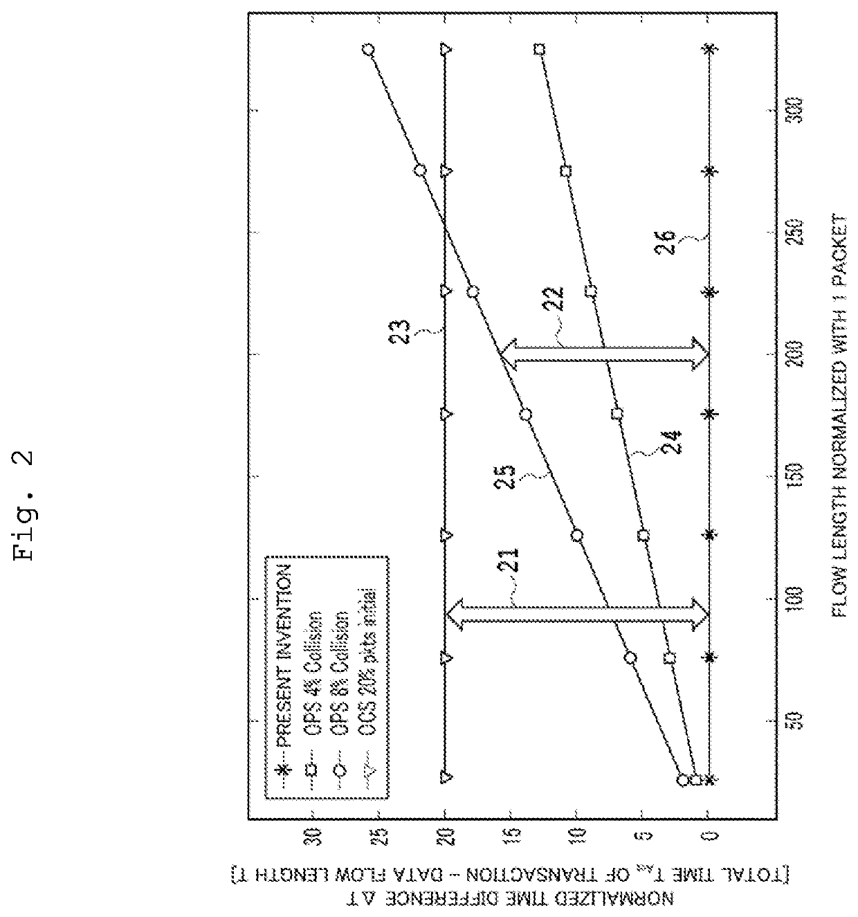
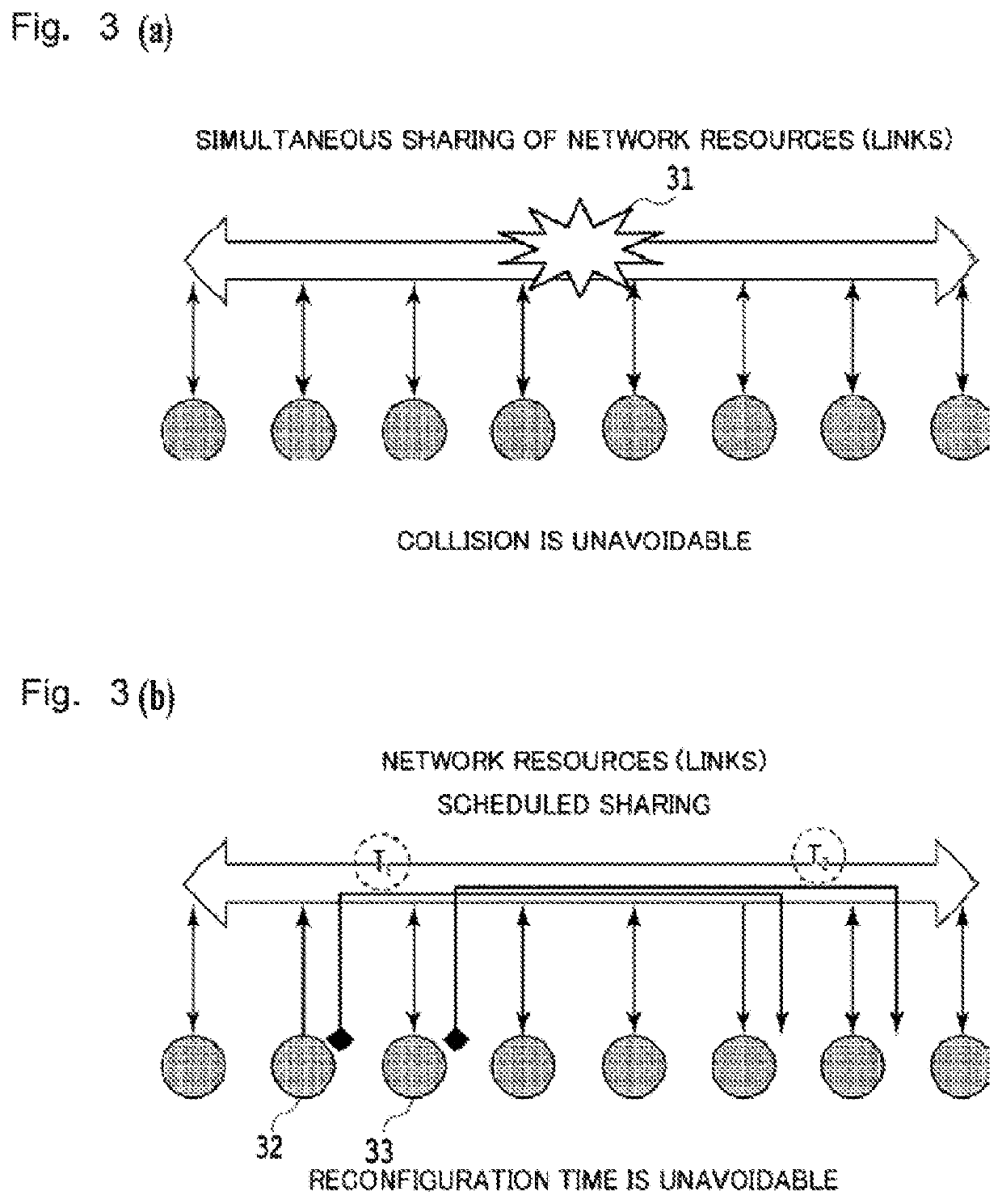
In the OPS scheme, the setting time as in the case of the OCS is not necessary, but a possibility of packets colliding with a certain probability is unavoidable.
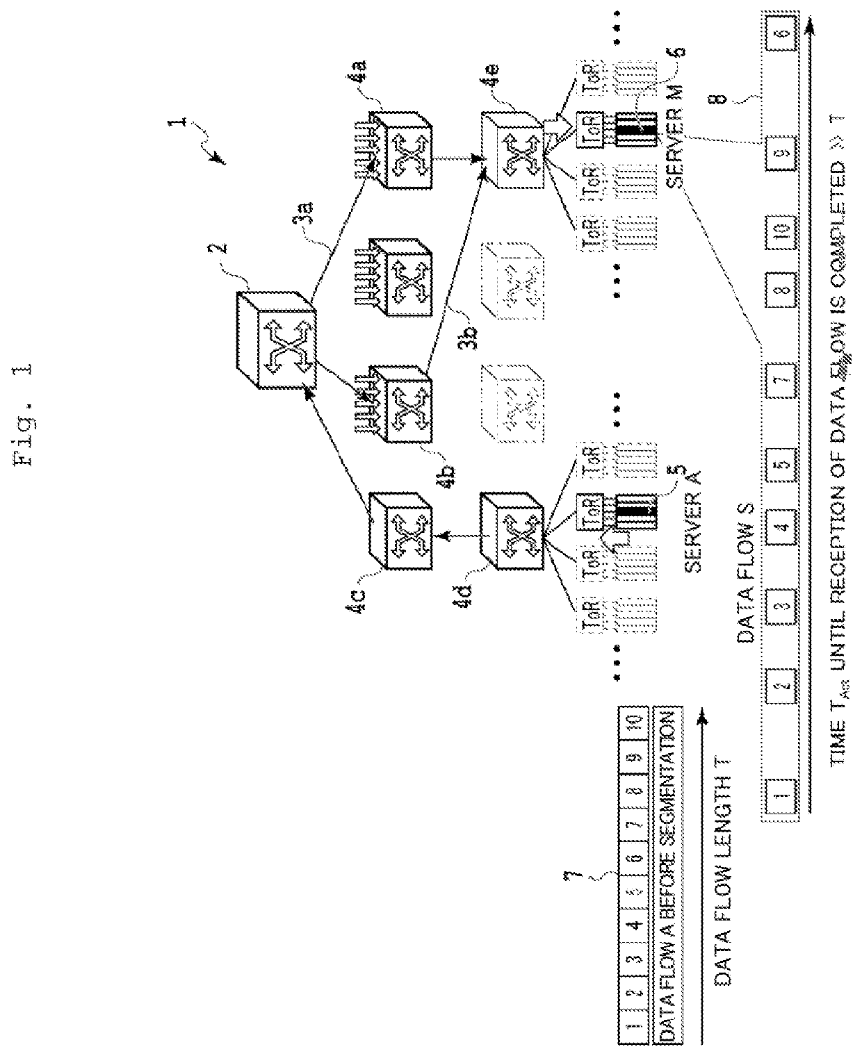
In the OCS scheme, the FOM value is very bad in a short data flow of several packets.
That is, the FOM value becomes worse as the data flow becomes longer.

Method used


Image

  • Optical Network, Optical Transport System, and Optical Node Included Therein
  • Optical Network, Optical Transport System, and Optical Node Included Therein
  • Optical Network, Optical Transport System, and Optical Node Included Therein

Examples


first embodiment

[0072]A configuration of an optical network according to the first embodiment in which the most basic concepts of the above-described present invention are used as it is will be described in more detail. A C band (1530 to 1565 nm) and an L band (1565 to 1625 nm) are wavelength bands which are most widely used at present to realize low propagation loss and optical signal transmission over optical fibers. Usable full-wavelength bands of the bands are segmented into smaller sub-band sets generally called “channels” in accordance with a fixed grid method. The number of network nodes which can be supported directly using the scheme of the optical network according to the present invention is limited by a total number of channels in the above-described C and L bands. For example, considering an example in which only the C band is used, the optical network based on the approach of the present invention can realize supporting a maximum of 80 network nodes. Further, by adding the L band, the...

second embodiment

[0077]As the first embodiment is described above, as illustrated in FIG. 6, the following features are based on the scheme of the optical network according to the present invention. Here, the features are that label-based switching is used on a dedicated wavelength channel associated for each source node. In the configuration of the optical network according to the embodiment, a first idea that the same wavelength can be reused without occurrence of collision in a network is introduced. To design an optical route in which the same wavelength is used to avoid collision of a data flow is a basis of this idea.

[0078]FIG. 7 is a diagram illustrating a basic configuration of an optical network according to a second embodiment of the present invention. In FIG. 7, an approach in a ring network 70 with the simplest configuration, that is, an optical network with a 1-dimensional torus topology configuration, will be described. The ring network 70 has a configuration in which eight nodes from ...

third embodiment

[0106]FIG. 18 is a diagram illustrating a structure for further reducing the number of wavelengths by parallelization of optical networks. FIG. 18 illustrates a state in which a wavelength is reused because of only application of the 2-dimensional torus network according to the second embodiment before the parallelization of the optical networks is applied. A 2-dimensional torus network 180 includes four nodes in each torus network of row (the vertical direction) and also includes four nodes in each torus network in a column (the horizontal direction). Four nodes of nodes 181-1 to 181-4 use the same wavelength λ1 four times and are referred to as a group A. Four nodes of nodes 182-1 to 182-4 also use the same wavelength λ2 four times and are referred to as a group B. In the optical network according to the embodiment, the number of wavelength is further reduced using one common wavelength by parallelizing optical fibers between a first group in which the wavelength λ1 is repeated an...


PUM


Abstract

In optical transmission schemes of the related art, there is a problem of delay dependency on an overhead or a flow size. In a DC network and a supercomputer network, an OCS scheme and an OPS scheme remain in an examination stage. A network of the electrical packet switching is still a main stream. In a scheme of sharing links using a dedicated wavelength, a considerable number of wavelengths is also necessary to provide full connectivity. The number of wavelengths cannot be realized and an unrealistic number considering the usable number of wavelengths such as current used C bands. In an optical network and an optical transmission system of the present invention, burst mode data transmission in which a label-based switching on an exclusively reserved dedicated wavelength is used is performed. Each node has a uniquely allocated wavelength, and thus traffics coexisting in all the network nodes do not collide. By using an optical label processor, an overhead time for establishing links between nodes is unnecessary. Reuse of the same wavelength results in further decrease in the number of wavelengths.

Description

BACKGROUND ART[0001]The present invention relates to an optical network, an optical node used therein, and an optical transmission scheme for a data flow using light.[0002]Data centers that store and process an explosive increase of data traffic are becoming more and more important. A data center is a generic name specifically for facilities in which computers (main frames, minicomputers, servers, and the like), data communication devices, and the like are installed and operated. In data centers, data center services are supplied to mainly monitor, operate, and manage information systems of companies, for example. Data centers substantially support information communication technology and systems to support trends such as virtualization technologies, cloud services, and big data.[0003]Optical switching is a technology for providing a solid foundation to realize dynamic operations in a network of a data center (DC) or a supercomputer. However, to overcome restrictions on optical hard...

Claims


Application Information

Patent Timeline
Patent Type & Authority Applications(United States)
IPC IPC(8): H04B10/275H04L12/42H04Q3/52
CPCH04B10/275H04Q3/526H04L12/42H04Q3/52H04J14/0258H04J14/0267H04Q11/0062H04Q2011/0077
Inventor SALAH, IBRAHIMHASHIMOTO, TOSHIKAZUSHIGEMATSU, SATOSHI
Owner NIPPON TELEGRAPH & TELEPHONE CORP
Why Eureka
Try Eureka