A propulsion system for a multirotor aircraft

a multi-rotor aircraft and propulsion system technology, applied in the direction of vertical landing/take-off aircraft, sustainable transportation, transportation and packaging, etc., can solve the problems of reduced payload capacity, reduced flight time, and reduced electrical energy, so as to increase the performance of the system and reduce the fuel consumption

a multi-rotor aircraft and propulsion system technology, applied in the direction of vertical landing/take-off aircraft, sustainable transportation, transportation and packaging, etc., can solve the problems of reduced payload capacity, reduced flight time, and reduced electrical energy, so as to increase the performance of the system and reduce the fuel consumption

US20210339850A1Pending Publication Date: 2021-11-04AEROSPACE HLDG INC

Image

  • A propulsion system for a multirotor aircraft
  • A propulsion system for a multirotor aircraft
  • A propulsion system for a multirotor aircraft

Examples


Embodiment Construction

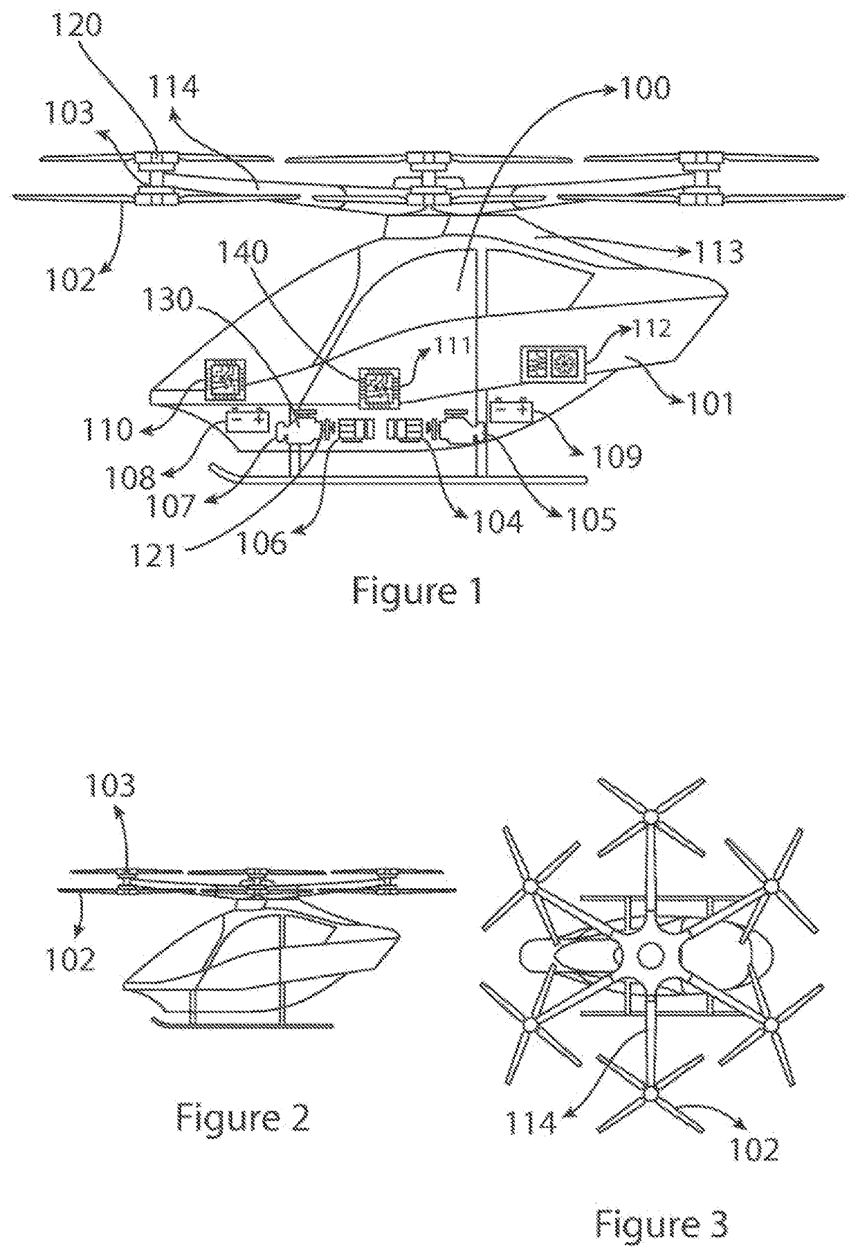
[0054]Referring now to FIG. 1 of the drawings there is shown, generally indicated as 100 a multirotor aircraft. The multirotor aircraft 100 includes a propulsion system 130 embodying a first aspect of the invention. The aircraft comprises a fuselage 101, the propulsion system 130 which comprises one or more propulsion assemblies 120 for providing thrust to the multirotor aircraft 100. The propulsion assemblies 120 are typically coupled to the multirotor aircraft through a plurality of arms 114. Preferably the multirotor aircraft 100 comprises a plurality of propulsion assemblies 120. In a preferred embodiment, as shown in FIGS. 1 to 3, the multirotor aircraft comprises six arms 114 with each arm comprising two propulsion assemblies 120, this can be seen further in FIGS. 2 and 3. However it should be understood that in alternative embodiments (not shown) each arm 114 may include only one propulsion assembly 120 or more than two propulsion assemblies 120 and if further arms 114 are pr...


PUM


Abstract

A propulsion system for a multirotor aircraft, the propulsion system comprising: at least one power generation module configured to provide a first source of electrical power to one or more propulsion assemblies of the multirotor aircraft; a control system which is configured to determine the required electrical power demand of the propulsion assembly and calculate a predicted electrical power demand for a following period of time; wherein the control system is configured to alter the electrical power produced by the power generation module such as to produce a power envelope which comprises the electrical power produced by the power generation module corresponding to the predicted electrical power demand; wherein the control system is configured to determine if the power envelope meets the required electrical power demand; and wherein when the power envelope is less than the required electrical power demand the control system is configured to selectively connect a second source of electrical power for supplying power to the propulsion assembly such as to compensate for the difference between the power envelope and the required electrical power demand.

Description

FIELD OF THE INVENTION[0001]This invention relates to a propulsion system for a multirotor aircraft and in particular a propulsion system for a multirotor aircraft which comprises a hybrid propulsion system.BACKGROUND TO THE INVENTION[0002]Multirotor aircraft (or rotary-wing aircraft) are aircraft which use more than two rotors for propulsion, their main flight characteristic being the ability of vertical takeoff and landing. Unlike traditional rotary-wing aircraft (such as the helicopter), multirotor aircraft are equipped with a distributed electrical propulsion (DEP) system which consists of several motors which are mechanically linked to the propellers, as well as an electronic system which controls stability by varying the speed of the propellers, and an energy source (electrical or chemical).[0003]The advantages of multirotor aircraft, when compared to traditional rotary-wing aircraft, consist of the absence of transmission mechanisms for both the main and the tail rotors (redu...

Claims


Application Information

Patent Timeline
04 Nov 2021
Publication
US20210339850A1
IPC
B64C27/10; B64D27/24
CPC
B64C27/10; B64D2027/026; B64D27/24; B64C29/0025; Y02T50/40; Y02T50/60; B64D27/026; B64D2221/00
Inventors
PREDONU, ALEXANDRU; VINEREANU, DACIAN IOAN