
SBS Suppression and Electronic Path Length Matching in Coherent Beam Combining

Pending Publication Date: 2021-11-11
MASSACHUSETTS INST OF TECH
View PDF2 Cites 1 Cited by
  • Summary
  • Abstract
  • Description
  • Claims
  • Application Information

AI Technical Summary

Benefits of technology

The patent text describes a method and system for combining two laser beams to create a high-power laser beam. The method uses binary modulation patterns, such as phase modulation, to compensate for any path length mismatch between the two laser beams. This modulation pattern is applied to each arm of the interferometer, which simplifies the fabrication tolerances required for the system and allows the use of a wider range of laser sources. The use of a seed laser source with a long coherence length reduces the importance of the physical lengths of the fibers in the system. The technical effects of the invention include improved combining efficiency and reduced fabrication precision requirements for the coherent beam combining system.

Problems solved by technology

Electronically tuning the delay of the modulation applied to different arms of the coherent beam combining system circumvents bandwidth scaling compatibility problems and the time-consuming nature of the current path length matching methods used in coherent beam combining systems.

Method used


Image

  • SBS Suppression and Electronic Path Length Matching in Coherent Beam Combining
  • SBS Suppression and Electronic Path Length Matching in Coherent Beam Combining
  • SBS Suppression and Electronic Path Length Matching in Coherent Beam Combining

Examples


Embodiment Construction

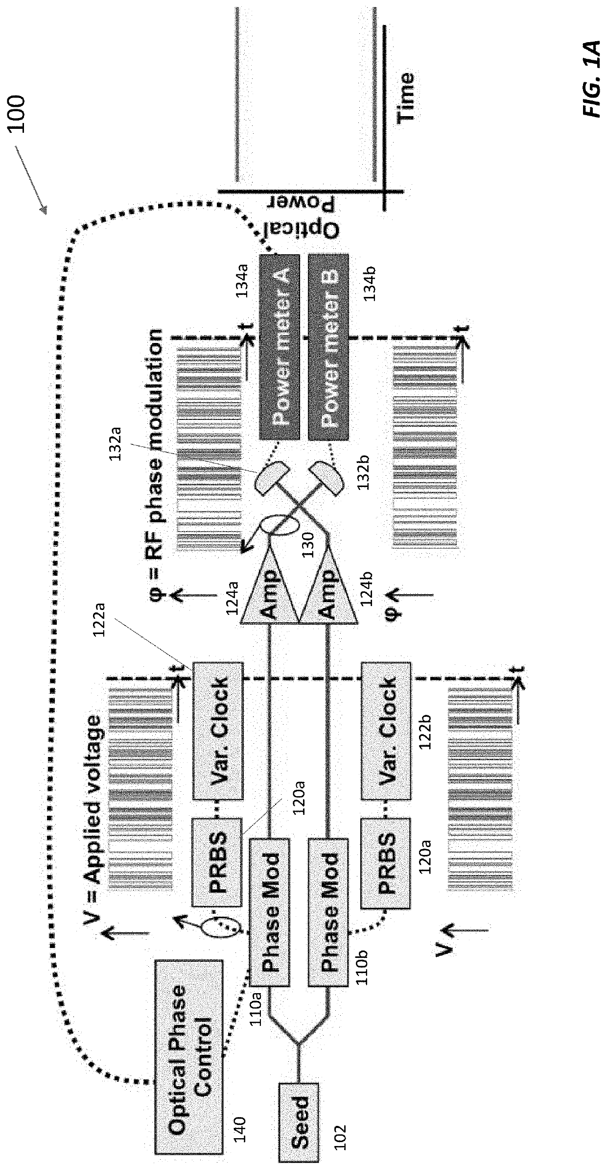
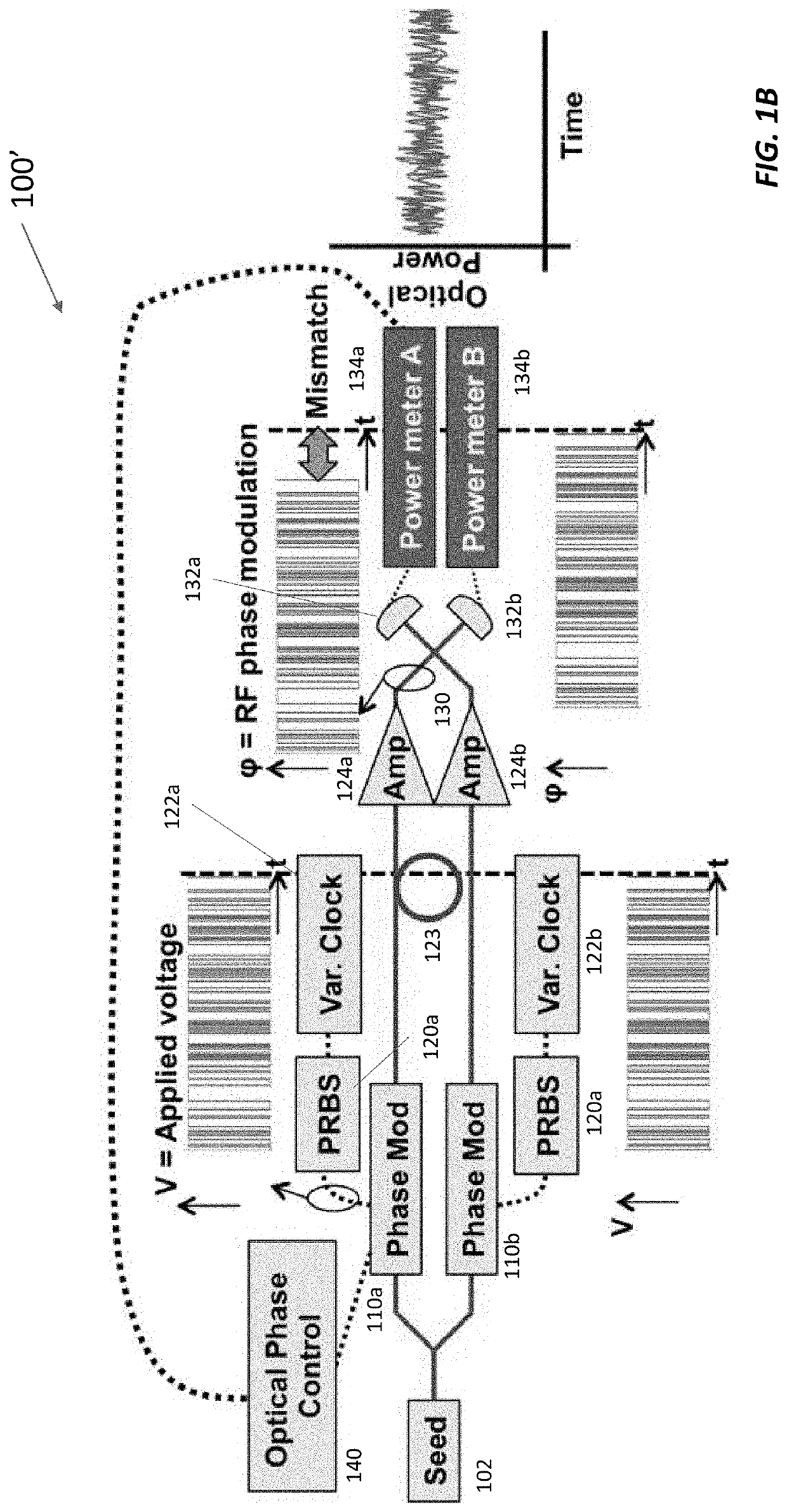
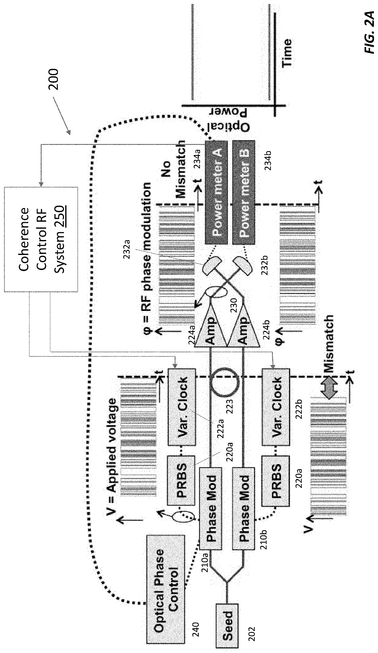
[0031]FIG. 1A shows a coherent beam combining system 100 with two channels or arms, each of which contains a fiber amplifier 124a, 124b (collectively, fiber amplifiers 124). (Other coherent beam combining systems may have tens or even hundreds of parallel arms for higher power output.) The fiber amplifiers 124 are seeded with respective copies of seed laser beam from a fiber-coupled seed laser 102. The fiber amplifiers 124 amplify these copies, and a beam splitter 130 combines them to produce a high-power output at port A as measured by photodetector 132a coupled to power meter A / 134a and little or no power at port B as measured by photodetector 132b coupled to power meter B / 134b (collectively, power meters 134).

[0032]A fiber-coupled phase modulator 110a, 110b (collectively, phase modulators 110) is placed before the amplifier 124a, 124b in each arm of system 100 to broaden the linewidth of the laser beams with pseudo-random bit sequence (PRBS) modulation in order to suppress SBS. E...


PUM


Abstract

In coherent beam combining, the beams can be phase-modulated with a pseudo-random bit sequence (PRBS) to prevent stimulated Brillouin scattering (SBS) downstream. To coherently combine the phase-modulated beams, however, the PRBS waveforms should be true-time-delayed to within a small fraction of the bit duration. Traditionally, this true time delay is achieved by cutting optical fibers to length or with optical trombones. But trimming fibers is hard to do precisely, and optical trombones have large insertion loss. In addition, the path length mismatch varies as the fibers heat up and / or vibrate. Here, the beams are generated from a kilohertz linewidth seed split among N>1 (e.g., N=100) arms. Each arm is phase-modulated with a separate copy of the unique PRBS pattern. The relative phase of the PRBS patterns is stabilized by phase-locking the master oscillators used to read out the PRBS patterns. The PRBS patterns can be phase shifted with respect to one another to compensate for physical path length mismatches of the optical fibers. Scanning the relative phase of the PRBS pattern used to modulate different arms yields a cross-correlation peak in combined power when the phases are matched at the combination plane.

Description

[0001]CROSS-REFERENCE TO RELATED APPLICATION(S)[0002]This application claims the priority benefit, under 35 U.S.C. 119(e), of U.S. Application No. 63 / 021,933, which was filed on May 8, 2020 and is incorporated herein by reference in its entirety for all purposes.GOVERNMENT SUPPORT[0003]This invention was made with Government support under Grant No. FA8702-15-D-0001 awarded by the U.S. Air Force. The Government has certain rights in the invention.BACKGROUND[0004]Fiber amplifiers operating at about 1.5 kW and about 15 GHz linewidth have been available since the mid-2000s. The beams from several of these fiber amplifiers can be combined coherently such that the fiber amplifiers form a High Energy Laser (HEL) system. A spectral linewidth of 15 GHz enables suppression of stimulated Brillouin scattering (SBS) in the fiber amplifiers; however, use of such broadband optical signals in beam combination systems also requires precise and very time consuming matching of the optical path lengths...

Claims


Application Information

Patent Timeline
IPC IPC(8): H01S3/23H01S3/13
CPCH01S3/2308H01S3/1307H01S3/1305H01S3/2383H01S3/1003H01S3/0085H01S2301/03H01S3/06754
Inventor LANGSETH, JASON E.BENEDICK, ANDREWTROTZ, SETH
Owner MASSACHUSETTS INST OF TECH
Learn More