Constant velocity joint for vehicle

a constant velocity joint and vehicle technology, applied in mechanical devices, couplings, transportation and packaging, etc., can solve the problems of increasing the bearing drag torque, affecting the sealing effect of the bearing, so as to reduce the overlap amount and reduce the overlap of the bearing seal.

Pending Publication Date: 2021-12-02
HYUNDAI WIA
View PDF3 Cites 1 Cited by
  • Summary
  • Abstract
  • Description
  • Claims
  • Application Information

AI Technical Summary

Benefits of technology

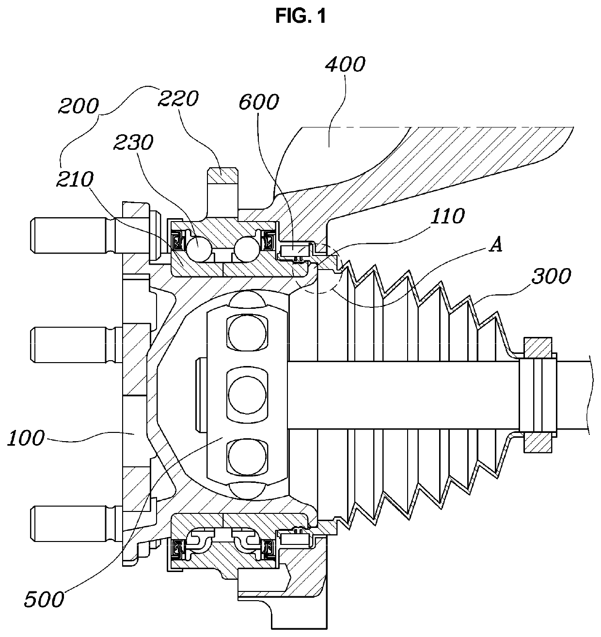
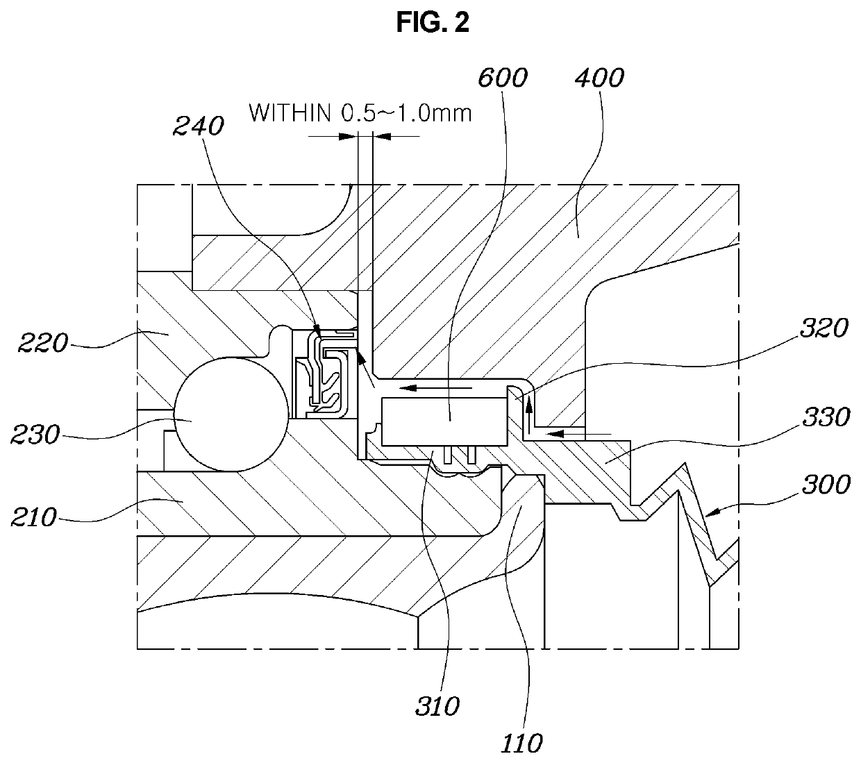
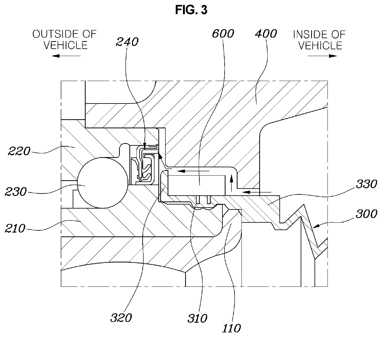
[0016]According to the present disclosure, since the boot lip protrudes toward the knuckle from one or more of the ends of the band seat which face the outside or the inside of a vehicle, it is possible to prevent foreign substances that enter between the boot and the knuckle from entering the bearing assembly. Further, since the movement path of foreign substances entering between the boot and the knuckle is bent like a labyrinth, even if foreign substances enter from the outside, it is possible to reduce the foreign substances entering the bearing assembly.
[0017]Further, according to the structure, since foreign substances entering between the boot and the knuckle is prevented from entering the bearing assembly, the ability to seal the bearing assembly can be maintained even if the overlap amount of the bearing seal is reduced.
[0018]Further, when the amount of overlap of the bearing seal is reduced, drag torque of the bearing assembly can be decreased, whereby the entire fuel efficiency of a vehicle can be improved.

Problems solved by technology

If a foreign substance enters a constant velocity joint from the outside, the foreign substance may enter a bearing assembly through a bearing seal, which may cause abnormal noise or shaking of the bearing, and thus may damage the bearing.
In order to solve this problem, a lip of the bearing seal is overlapped by a maximum amount to seal a bearing assembly, but there is a problem that bearing drag torque is increased.

Method used


Image

  • Constant velocity joint for vehicle
  • Constant velocity joint for vehicle
  • Constant velocity joint for vehicle

Examples


Embodiment Construction

[0026]It is understood that the term “vehicle” or “vehicular” or other similar term as used herein is inclusive of motor vehicles in general such as passenger automobiles including sports utility vehicles (SUV), buses, trucks, various commercial vehicles, watercraft including a variety of boats and ships, aircraft, and the like, and includes hybrid vehicles, electric vehicles, plug-in hybrid electric vehicles, hydrogen-powered vehicles and other alternative fuel vehicles (e.g. fuels derived from resources other than petroleum). As referred to herein, a hybrid vehicle is a vehicle that has two or more sources of power, for example both gasoline-powered and electric-powered vehicles.

[0027]The terminology used herein is for the purpose of describing particular embodiments only and is not intended to be limiting of the disclosure. As used herein, the singular forms “a,”“an” and “the” are intended to include the plural forms as well, unless the context clearly indicates otherwise. It wil...


PUM


Abstract

A constant velocity joint for a vehicle may include: a hub housing combined with the constant velocity joint in the hub housing; a bearing assembly including an inner race fitted on an outer surface of the hub housing, an outer race spaced a predetermined distance apart from the inner race and fitted on a knuckle, and a power transmission member disposed between the inner race and the outer race; and a boot having a band seat that is positioned on the inner race of the bearing assembly, the boot having a fixing band fixed on a top of the boot and the boot being coupled to the inner race by the fixing band, where the boot includes a boot lip that is formed at one end or both ends of the band seat and protrudes toward the knuckle.

Description

CROSS REFERENCE TO RELATED APPLICATION[0001]The present application claims under 35 U.S.C. § 119(a) the benefit of Korean Patent Application No. 10-2020-0063714, filed on May 27, 2020, the entire contents of which are incorporated by reference herein.BACKGROUND(a) Technical Field[0002]The present disclosure relates to a constant velocity joint for a vehicle, more particularly, to the constant velocity joint for automotive use having a structure that can prevent foreign substances from entering the constant velocity joint from an outside.(b) Description of the Related Art[0003]In general, hubs and bearings are installed on tire wheels connected to a drive axle and used to support loads in up-down and front-rear directions of a vehicle and horizontal loads caused by turning of the vehicle. A constant velocity joint is installed on the drive axle of the vehicle and used to transmit power from a transmission to wheels. The constant velocity joint, a hub, and a bearing are usually separa...

Claims


Application Information

Patent Timeline
Patent Type & Authority Applications(United States)
IPC IPC(8): B60B27/00F16D3/84F16D3/30
CPCB60B27/0036B60B27/0073B60B2310/306F16D3/30B60B2900/5112F16D3/845F16D3/223F16D2003/22326F16C19/185F16C33/805F16C33/7883F16D3/84F16D3/221B60B27/0042F16C33/76F16D2300/12Y10S464/906
Inventor KIM, DONG WOO
Owner HYUNDAI WIA
Why Eureka
Try Eureka