
Inflatable kayak

Active Publication Date: 2021-12-16
JIANGSU JILONG SPORT & LEISURE PROD CO LTD
View PDF0 Cites 0 Cited by
  • Summary
  • Abstract
  • Description
  • Claims
  • Application Information

AI Technical Summary

Benefits of technology

The present patent is for an inflatable kayak that has low resistance during gliding, high strength, and is less prone to damage. The floor of the kayak is designed to reduce resistance at the ends, making it more attractive and easy to glide. The bottom reinforcing layer covers the joint of the floor and the gunwale, increasing the strength of the kayak and reducing the likelihood of damage. Additionally, the prow and stern have a stronger connection through the hatchway covers, which increase the overall strength of the kayak.

Problems solved by technology

The bow and the stern are lower than the middle of the hull, which makes the inflatable kayak difficult to glide because of a large resistance, and provides the kayak an unaesthetic appearance.
In addition, the inflatable kayaks are commonly made of a single layer of material, which is prone to be damaged and deflated because of frequently collisions, making them unusable.

Method used


Image

  • Inflatable kayak
  • Inflatable kayak
  • Inflatable kayak

Examples


first embodiment

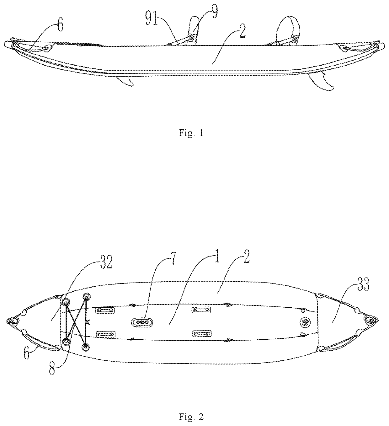
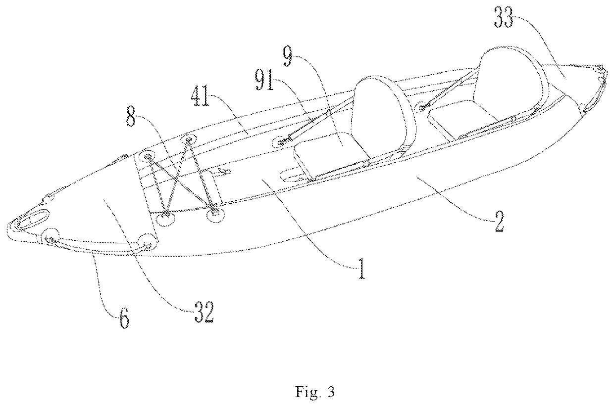
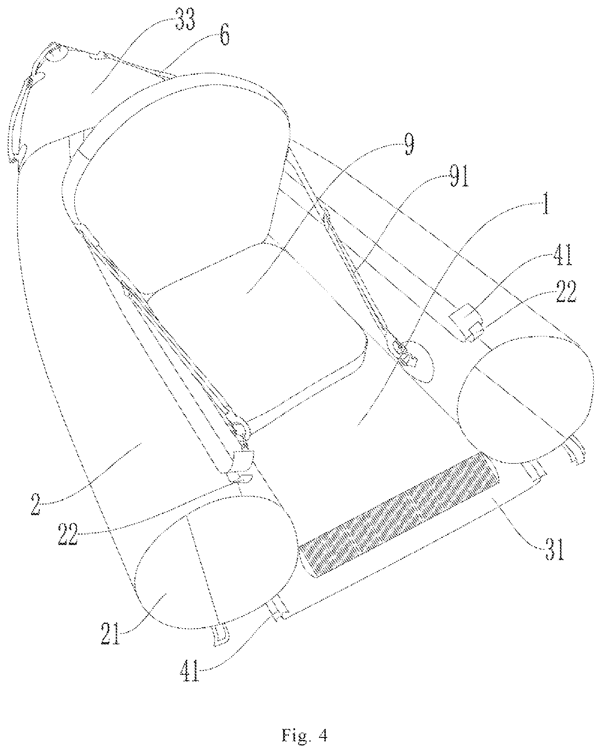
[0044]Please referring to FIGS. 1 to 4, the exemplary embodiment provides an inflatable kayak. The inflatable kayak includes an inflatable floor 1, two inflatable gunwales 2, and a reinforcing assembly.

[0045]The Inflatable floor 1 has two ends designed upward. The inflatable floor 1 is a drop stitch fabric floor made of high pressure resistant drop stitch fabric. An edge banding material is arranged at the edge of the drop stitch fabric and tightly connected to the two sides of the drop stitch fabric by sealant, to ensure the gas tightness of the inflatable floor 1. An inflation valve is defined on the upper surface of the inflatable floor 1 to facilitate inflating the inflatable floor 1 through the inflation valve.

[0046]The two ends of the inflatable floor 1 are designed upwards, so that the prow and the stern are higher than the middle of the hull, which reduces the resistance of the inflatable kayak in gliding, and makes the inflatable kayak look more attractive.

[0047]The two inf...

second embodiment

[0060]Please referring to FIGS. 5 to 7, the exemplary embodiment provides an inflatable kayak. The inflatable kayak includes an inflatable floor 1, two inflatable gunwales 2, and a reinforcing assembly.

[0061]The Inflatable floor 1 has two ends designed upward. The inflatable floor 1 is a drop stitch fabric floor made of high pressure resistant drop stitch fabric. An edge banding material is arranged at the edge of the drop stitch fabric and tightly connected to the two sides of the drop stitch fabric by sealant, to ensure the gas tightness of the inflatable floor 1. An inflation valve is defined on the upper surface of the inflatable floor 1 to facilitate inflating the inflatable floor 1 through the inflation valve.

[0062]The two ends of the inflatable floor 1 are designed upwards, so that the prow and the stern are higher than the middle of the hull, which reduces the resistance of the inflatable kayak in gliding, and makes the inflatable kayak look more attractive.

[0063]The two inf...


PUM


Abstract

The present disclosure provides an inflatable kayak. The inflatable kayak includes an inflatable floor having two ends defined upward; two inflatable gunwales arranged on the left and right sides of the inflatable floor, the height of the upper edge at both ends of the inflatable gunwale being higher than the height at the middle of the inflatable gunwale, allowing the height of the prow and the stern of the inflatable kayak to be no less than the height at the middle of the inflatable kayak; and a reinforcing assembly including a bottom reinforcing layer, a prow hatchway cover, and a stern hatchway cover, the bottom reinforcing layer at least covering the joints of the inflatable floor and the two inflatable gunwales. The prow hatchway cover connects the two inflatable gunwales at the prow, and the stern hatchway cover connects the two inflatable gunwales at the stern.

Description

FIELD OF THE PRESENT DISCLOSURE[0001]The present disclosure relates to the field of inflatable kayaks, and more particularly to an inflatable kayak.DESCRIPTION OF RELATED ART[0002]Kayak leisure sports have been widely existed abroad with people's constant pursuit of healthy and quality life, and gradually began to arise in China. Inflatable kayaks are more and more popular because of the advantages of light weight, foldability after air escape, portability, and easy to store.[0003]In related art, the inflatable kayak generally includes prow, hull, and stern connected successively. The bow and the stern are lower than the middle of the hull, which makes the inflatable kayak difficult to glide because of a large resistance, and provides the kayak an unaesthetic appearance. In addition, the inflatable kayaks are commonly made of a single layer of material, which is prone to be damaged and deflated because of frequently collisions, making them unusable.[0004]Therefore, it is desirable t...

Claims


Application Information

Patent Timeline
IPC IPC(8): B63B34/22B63B7/08
CPCB63B34/22B63B7/085B63B34/26B63B13/00B63B2029/043B63B7/08
Inventor BAI, HAOSHEN, WEITANG, SHANSHAN
Owner JIANGSU JILONG SPORT & LEISURE PROD CO LTD
Learn More