Anode active material and preparation method thereof, and device using the anode active material

a technology of anode active material and anode active material, which is applied in the field of energy storage, can solve the problems of poor conductivity of silicon, lowering the cycle performance of lithium ion batteries, and affecting the performance of lithium ion batteries, and achieves poor conductivity of silicon, lowering the cycle performance of lithium ion batteries, and causing a large mechanical stress

Pending Publication Date: 2022-02-17
NINGDE AMPEREX TECH
View PDF0 Cites 0 Cited by
  • Summary
  • Abstract
  • Description
  • Claims
  • Application Information

AI Technical Summary

Benefits of technology

[0004]Silicon has been considered to be the most probable lithium ion anode material for large-scale applications because of its reversible capacity of up to 4200 mAh / g. However, after several charge and discharge cycles, the silicon material undergoes a large volume change with the intercalation and deintercalation of lithium ions, and the volume expansion ratio may reach 300%, thereby generating huge mechanical stress. This will cause pulverization of silicon particles and debonding of the active material from a current collector, thereby lowering the cycle performance of a lithium ion battery. At the same time, the conductivity of silicon is poor, which will cause severe polarization and further lower its cycle performance.
[0005]At present, the main methods for solving the large volume change and poor conductivity during the cycle of silicon materials are nanocrystallization of silicon materials, complexing of silicon-containing materials with graphite or other materials (metal or non-metal) and optimization of binders for silicon anodes. However, the nano material is prone to agglomeration and has a large specific surface area (>100 m2 / g), thereby consuming more electrolyte to form a solid electrolyte interfacial film (SEI film), and causing problems of reduction of first coulombic efficiency and reduction of conductivity, which will limit the further application of the nano silicon material. The use of good electrical conductivity and ductility of materials such as graphite may greatly alleviate the volume expansion of the silicon material during the cycle and enhance the conductivity of a system. A silicon-containing composite material may play a certain restraining role in the early stage of the cycle. However, as the cycle progresses, the silicon expansion is not well suppressed, and the performance of the battery is drastically lowered. Moreover, the binder currently used still cannot match the huge stress (up to 1 Gpa) of silicon generated during the volume expansion and contraction, and the binder is prone to fatigue failure during the cycle.

Problems solved by technology

However, after several charge and discharge cycles, the silicon material undergoes a large volume change with the intercalation and deintercalation of lithium ions, and the volume expansion ratio may reach 300%, thereby generating huge mechanical stress.
This will cause pulverization of silicon particles and debonding of the active material from a current collector, thereby lowering the cycle performance of a lithium ion battery.
At the same time, the conductivity of silicon is poor, which will cause severe polarization and further lower its cycle performance.
However, the nano material is prone to agglomeration and has a large specific surface area (>100 m2 / g), thereby consuming more electrolyte to form a solid electrolyte interfacial film (SEI film), and causing problems of reduction of first coulombic efficiency and reduction of conductivity, which will limit the further application of the nano silicon material.
However, as the cycle progresses, the silicon expansion is not well suppressed, and the performance of the battery is drastically lowered.
Moreover, the binder currently used still cannot match the huge stress (up to 1 Gpa) of silicon generated during the volume expansion and contraction, and the binder is prone to fatigue failure during the cycle.

Method used


Image

  • Anode active material and preparation method thereof, and device using the anode active material
  • Anode active material and preparation method thereof, and device using the anode active material

Examples


Embodiment Construction

[0044]The present application will be described below in detail. It shall be understood that terms used in the specification and the annexed claims shall not be explained as limited to meanings in a common sense and dictionaries but be explained based on meanings and concepts corresponding to the technical aspects of the present application on the basis of the principle that the inventor is allowed to properly define the terms to make an optimum explanation. Therefore, the implementation solution in the specification and the description in the drawings are only specific examples used for the purpose of description rather than intentions to illustrate all technical aspects of the present application, and it shall be understood that, when the present application is filed, various alternative equivalents and variants may be completed thereto.

[0045]As used herein, the terms “substantially”, “generally”, “essentially” and “about” are used to describe and explain small variations. When be...


PUM

PropertyMeasurementUnit
diameteraaaaaaaaaa
diameteraaaaaaaaaa
diameter D50aaaaaaaaaa

Abstract

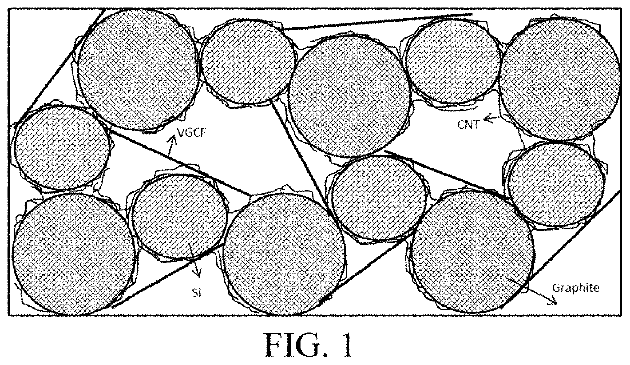
The present application relates to an anode active material and a preparation method thereof, and a device using the anode active material. The anode active material provided by the present application includes anode active particles having silicon element, a first conductive material and a second conductive material, wherein the first conductive material and the second conductive material form a three-dimensional conductive network structure, at least a portion of the anode active particles are accommodated in the three-dimensional conductive network structure, and a ratio of the total surface area of the first conductive material to the total surface area of the anode active particles is less than 1000. The capacity retention rate and expansion ratio of the anode active material with progression of the cycle are significantly improved.

Description

CROSS REFERENCE TO RELATED APPLICATIONS[0001]The present application is a National Stage application of PCT international application: PCT / CN2019 / 119436 which claims the benefit of priority from the China Patent Application No. 201910214567.1, filed on 20 Mar. 2019, the disclosure of which is hereby incorporated by reference in its entirety.BACKGROUND1. Field of the Invention[0002]The present application relates to the field of energy storage, and more particularly to an anode active material and a preparation method thereof, and a device using the anode active material.2. Description of the Related Art[0003]With the popularity of electronic products such as notebook computers, mobile phones, handheld game consoles and tablet computers, the requirements for electrochemical devices (for example, batteries) are more and more stringent. In the plurality of batteries, compared with lead-acid batteries, nickel-cadmium batteries, nickel-hydrogen batteries and the like, the lithium ion bat...

Claims


Application Information

Patent Timeline
Patent Type & Authority Applications(United States)
IPC IPC(8): H01M4/36H01M4/38H01M4/587H01M4/62H01M4/134H01M4/133H01M4/48H01M10/0525
CPCH01M4/364H01M4/366H01M4/386H01M4/587H01M2004/021H01M4/134H01M4/133H01M4/48H01M10/0525H01M4/625H01M4/621Y02E60/10H01M2004/027H01M4/483H01M4/13H01M4/622H01M4/623H01M4/0404
Inventor CHEN, ZHIHUANJIANG, DAOYICUI, HANGXIE, YUANSEN
Owner NINGDE AMPEREX TECH
Why Eureka
Try Eureka