Vcsel-based free space active optical transceiver component

a free space active, optical transceiver technology, applied in the field of optical communication, lasers or display devices, to achieve the effects of low cost, high transmission rate, and free space connection

Pending Publication Date: 2022-02-17
II VI DELAWARE INC
View PDF0 Cites 3 Cited by
  • Summary
  • Abstract
  • Description
  • Claims
  • Application Information

AI Technical Summary

Benefits of technology

[0003]Aiming at the situation of the prior art, the present invention aims to provide a VCSEL-based free space active optical transceiver component, which is low in cost, small in size, h in transmission rate, and capable of implementing free space high-speed signal transmission in a medium / short-range high-definition multimedia interface (HDMI) device.
[0022]By adopting the above technical scheme, compared with the prior art, the present invention has the beneficial effects as follows: with the VCSEL-based free space active optical transceiver component proposed in present invention, the transmission and reception of a short / medium-distance free space (wireless) high-speed optical communication signal can be implemented, and a single-channel transceiving rate may reach 10 Gbps or higher. The component may be used for implementing a free space high-speed signal transmission function in a short / medium-range HDMI device. In addition, the present invention also has the characteristics of free space connection, high transmission rate, low cost, small size, easy assembly and mass production, etc., and has a broad market prospect.

Problems solved by technology

However, in the future short / medium-distance application scenarios, because of the disadvantages of easy breakage, complex wiring, affected appearance, etc. of optical fibers, a free space optical signal transmission scheme is being paid more and more attention to and adopted by people, and it is expected to replace optical fiber transmission in many short / medium -distance fields in the future, among which important application scenarios include high-definition very-large-screen 4K and 8K televisions, VR and AR multimedia devices, etc.

Method used


Image

  • Vcsel-based free space active optical transceiver component
  • Vcsel-based free space active optical transceiver component
  • Vcsel-based free space active optical transceiver component

Examples


embodiment 1

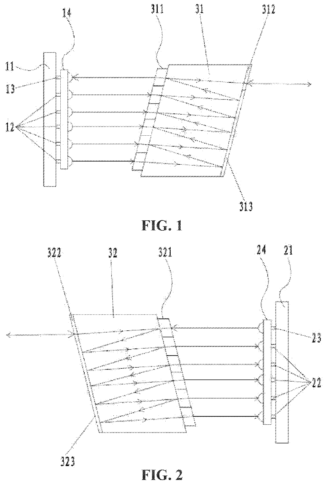
[0036]As shown in one of FIG. 1 and FIG. 2, a VCSEL-based free space active optical transceiver component of the present embodiment includes:

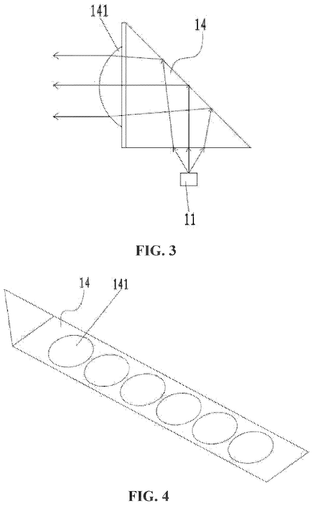
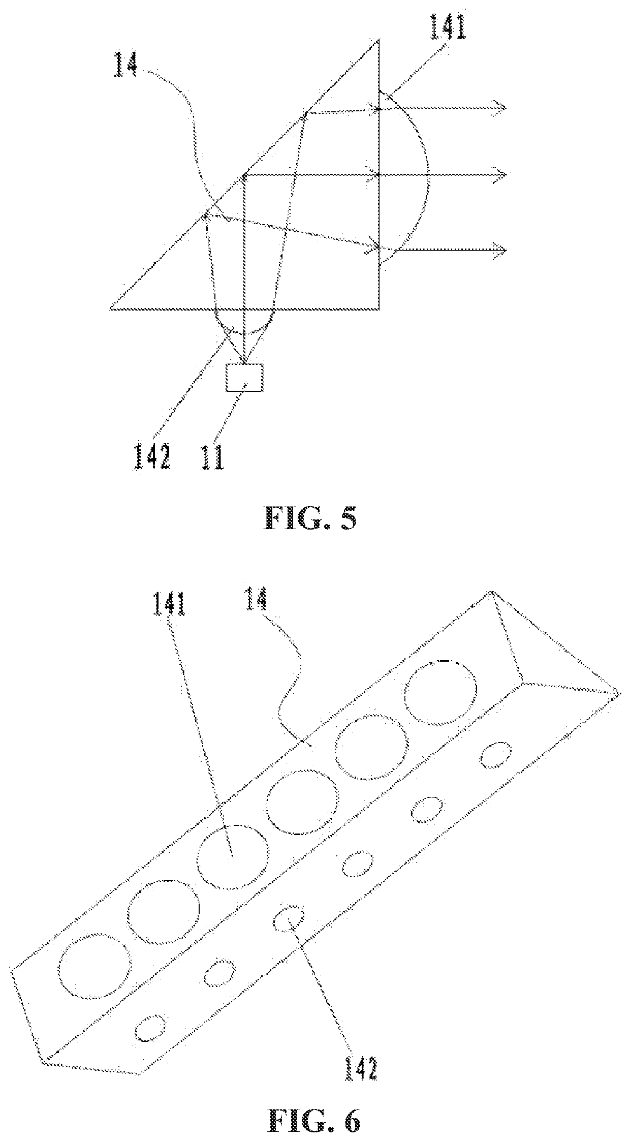
[0037]a transmitter that includes a plurality of VCSELs 12, at least one photodiode 13, a first focusing lens array 14, and a first printed circuit board 11, the plurality of VCSELs 12 and the photodiode 13 being arranged in an array on the first printed circuit board 11, and the first focusing lens array 14 being opposite to the plurality of VCSELs 12 and the photodiode 13 one by one and being configured to collimate transmitted signal light or focus received signal light; and

[0038]a receiver that includes a plurality of photodiodes 22, at least one VCSEL 23, a second focusing lens array 24, and a second printed circuit board 21, the plurality of photodiodes 22 and the VCSEL 23 being arranged in an array on the second printed circuit board 21, and the second focusing lens array 24 being opposite to the plurality of photodiodes 22 and the VCSEL...

embodiment 2

[0054]With reference to FIG. 7, the present embodiment is substantially the same as Embodiment 1 except that the first Z-BLOCK prism and the second Z-BLOCK prism of Embodiment 1 are replaced by a band-pass filter array 31 in the present embodiment. The band-pass filter array 31 is arranged at the receiver, the band-pass filter array 31 is provided with filters 32 with different working wavelengths and is opposite to the second focusing lens array 24, the plurality of VCSELs 12 on the first printed circuit board 11 of the transmitter transmit signal light with different working wavelengths, the signal light is collimated by the first focusing lens array 14 and then input to the corresponding filter 32 of the corresponding band-pass filter array 31, and the filter 32 allows the signal light adapted to the working wavelength thereof to penetrate through (the band-pass filter can achieve the passage of a light signal with the required wavelength and the isolation of a non-required light...

embodiment 3

[0061]The present embodiment is another implementation scheme of the inventive concept, and with reference to one of FIG. 8 to FIG. 12, the component includes:

[0062]a transmitter that includes a plurality of VCSELs 12, at least one photodiode 13, a first optical system 14, and a first printed circuit board 11, the plurality of VCSELs 12 and the photodiode 13 being arranged in an array on the first printed circuit board 11, and an incident end of the first optical system 14 being opposite to the plurality of VCSELs 12 and the photodiode 13 and being configured to collimate or focus received signal light; and

[0063]a receiver that includes a plurality of photodiodes 22, at least one VCSEL 23, a second optical system 25, and a second printed circuit hoard 21, the plurality of photodiodes 22 and the VCSEL 23 being arranged in an array on the second printed circuit board 21, an incident end of the second optical system 25 being configured to receive a light signal transmitted from an emer...


PUM

PropertyMeasurementUnit
thicknessaaaaaaaaaa
wavelength rangeaaaaaaaaaa

Abstract

A vertical cavity surface emitting laser (VCSEL)-based free space active optical transceiver component includes; a transmitter and a receiver. The transmitter includes first VCSELs, at least one first photodiode, a first focusing lens array or optical system (14), and a first printed circuit board. The receiver includes second photodiodes, at least one second VCSEL, a second focusing lens array or optical system, and a second printed circuit board. The transmission and reception of a short / medium-distance free space (wireless) high-speed optical communication signal can be implemented, and a single-channel transceiving rate may reach 10 Gbps or higher. The component may be used for implementing a free space high-speed signal transmission function in a short / medium-range high-definition multimedia interface (HDMI) device.

Description

TECHNICAL FIELD[0001]The present invention belongs to the field of optical communication, laser, or display devices, and in particular, to a vertical cavity surface emitting laser (VCSEL)-based free space active optical transceiver component.BACKGROUND ART[0002]In optical communication, transmitters and receivers of almost all optical transceivers are connected by optical fibers, including single-mode optical fibers, multi-mode optical fibers, plastic optical fibers, etc. Optical fiber connection has the advantages of low loss, small interference from an external environment, a transmission direction changeable at any time, etc., and it is very suitable for the connection of conventional optical communication. However, in the future short / medium-distance application scenarios, because of the disadvantages of easy breakage, complex wiring, affected appearance, etc. of optical fibers, a free space optical signal transmission scheme is being paid more and more attention to and adopted ...

Claims


Application Information

Patent Timeline
Patent Type & Authority Applications(United States)
IPC IPC(8): H01S5/42H01S5/026
CPCH01S5/423H01S5/0267H01S5/0262H04B10/40G02B6/42H01S5/4012G02B19/0014G02B19/0057G02B3/0006G02B27/30H04B10/1143G02B6/4296G02B6/4206G02B6/4215G02B3/0037G02B3/04G02B5/04H04B10/506H04B10/112
Inventor LU, GUANGLONGREN, CEJIA, XUWANG, ZIHANG
Owner II VI DELAWARE INC
Why Eureka
Try Eureka