Compression tool for dental implantation sites, and a method of using the same

a compression tool and dental implant technology, applied in the field of tools, can solve the problems of reducing the heat generation of the entire borehole drilling process, reducing the efficiency of the entire drilling process, so as to reduce the amount of heat generated

Pending Publication Date: 2022-02-24
CARMEX PRECISION TOOLS
View PDF0 Cites 0 Cited by
  • Summary
  • Abstract
  • Description
  • Claims
  • Application Information

AI Technical Summary

Benefits of technology

[0012]The foregoing and other needs are satisfied by means of the new compression tool which comprises a shank or body portion defined around a longitudinally extending axis, and wherein the lower section of the shank or body portion comprises a plurality of longitudinally extending left-handed flute structures disposed around the external surface portion of the lower section of the shank or body portion within a circumferential array but wherein the plurality of flute structures are not spaced equiangularly around the longitudinal axis of the drill or osteotome. More particularly, it is seen that the plurality of flute structures may, for example, comprise six (6) flute structures, although the precise number of flute structures may vary, and that each flute structure comprises a right-hand leading crest or cutting edge portion, and trailing margin and relieved land portions. The margin portion is effectively disposed within the same tangential plane or circumferential locus as that of the leading crest or cutting edge portion, as considered in connection with the inner circumferential wall of the bone material defining the dental implantation site, while the relieved land portion is angled away from the tangential leading crest or cutting edge portion, and the margin portion, so as to effectively reduce the surface area disposed in contact with the inner circumferential wall of the bone material defining the dental implantation site which thereby, in turn, reduces the amount of heat generated during the compression or densification process of the procedure. The leading crest or cutting edge portion also leads into an arcuately configured groove or pocket section of each flute structure so as to, effectively entrap and accumulate minute particles of bone which have been removed by means of the leading crest or cutting edge portions of the flute structures.
[0013]As a result of this integral composite flute structure, comprising the left-handed flutes with the right-handed cutting edges, as well as the margin, relieved, and grooved or pocket sections, the leading crest or cutting edge portions will therefore effectively remove minute particles of bone from the innermost circumferential wall surface of the bone surrounding the dental implantation site, such particles will then be effectively prevented from being evacuated from the implantation site so as to accumulate within the arcuately configured groove or pocket sections of the flute structures, and the margin portions will then compress such minute particles of bone radially outwardly and into the bone material circumferentially surrounding the implantation site, thereby enhancing the densification of such bone material circumferentially surrounding and defining the implantation site by means of compression and compaction. It is additionally noted that the lower fluted section of the shank or body portion is tapered a predetermined amount as one proceeds from the distal end, at which the flute structures begin, to the apical end, which is adapted to be inserted within a rotary motor or other power source so as to imp

Problems solved by technology

However, there are several drawbacks to the system and method disclosed within these patents.
The use of such multiple drills or osteotomes renders the entire borehole drilling and finishing or burnishing process unnecessarily prolonged and tedious since the dental surgeon will need to periodically exchange several drills or osteotomes for other drills or osteotomes, having incrementally larger diametrical extents, until the drilled borehole has achieved the desired diametrical extent.
This equiangularly spaced, circumferential array of the flutes has been discovered to result in the chattering or vibration of the drill or osteotome as it undergoes its rotational movement.
It is known in the art that such monitoring techniques are conventionally employed by dental surgeons so as to ensure that the drill or osteotome has not reached depth levels beyond the intended depth level, which could be dangerous.
However, not only are such markings difficult to see during the actual drilling process, but in addition, such entails an obvious discontinuous procedural process of drilling, determining the depth to which the dental surgeon has drilled, continue drilling deeper, again determining the depth to which the dental surgeon has drilled further, and the like, thereby rendering the drilling process imprecise, tedious, and prolonged.
Again, however, this start, stop, and switch procedure is somewhat tedious and prolongs the formation of the desired osteotomy.
Still yet further, in accordance with the aforenoted manual, the drill or osteotome of Versah® is rotated at relatively high speeds comprising 800-1500 RPM, and requires constant water irrigation in order to prevent the implantation site from being subjected to significantly elevated temperatures, or else, such significantly elevated temperatures could potentially lead to the development of gangrene o

Method used


Image

  • Compression tool for dental implantation sites, and a method of using the same

Examples


Embodiment Construction

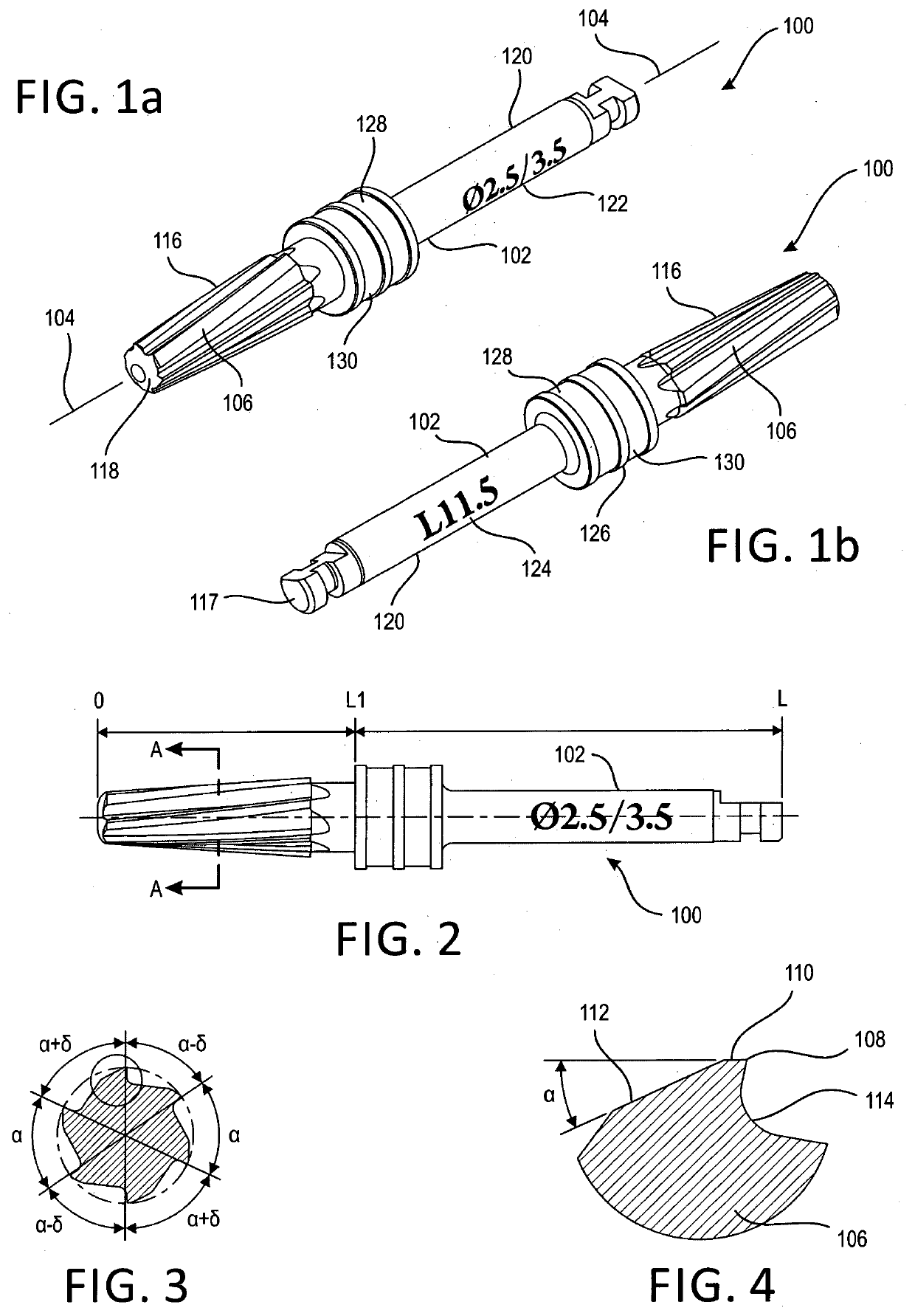
[0021]With reference now being made to the drawings, and more particularly to FIGS. 1a-4, a new compression tool is disclosed and is generally indicated by the reference character 100. More particularly, it is seen that the new compression tool 100 comprises a shank or body portion 102 which is defined around a longitudinally extending axis 104, and wherein the lower section of the shank or body portion 102 comprises a plurality of longitudinally extending flute sections 106 disposed around the external surface portion of the lower section of the shank or body portion 102 within a circumferential array. It is to be noted that the plurality of flute sections 106 are not spaced equiangularly around the longitudinal axis 104 of the drill or osteotome 100 as can best be appreciated from FIG. 3, wherein it is clearly illustrated that the angular spacing defined between some adjacent flute sections is denoted by means of the angle cc, whereas the angular spacing defined between some other...


PUM


Abstract

A compression tool for performing a finishing procedure, within a bore hole formed within a human jawbone so as to serve as an implantation site for a dental implant, by compression and densification processes, comprises a tapered body portion, and a plurality of flute sections disposed the body portion, wherein, when the compression tool is rotated in a clockwise direction and simultaneously axially inserted into the bore hole, the plurality of flute sections, which comprise structure for continuously cutting bone material from bone mass surrounding and defining the bore hole formed within the human jawbone, for accumulating the bone material so as to prevent the bone material from being evacuated from the implantation site, and for immediately compressing the bone material, cut from the bone mass surrounding and defining the bore hole formed within the human jawbone, back into the bone mass surrounding and defining the bore hole formed within the human jawbone will compress, compact, and enhance the density of the bone mass surrounding and defining the bore hole formed within the human jawbone.

Description

FIELD OF THE INVENTION[0001]The present invention relates generally to tools, and more particularly to a new compression tool for use in connection with the enhancement of the thickness and density of the bone sections forming or surrounding a dental implantation site.BACKGROUND OF THE INVENTION[0002]Various medical drills or osteotomes are of course known in the art. Examples of some known drills or osteotomes can be appreciated from U.S. Pat. No. 10,039,621 which issued to Huwais on Aug. 7, 2018; U.S. Pat. No. 9,028,253 which issued to Huwais on May 12, 2015; and U.S. Pat. No. 9,022,783 which issued to Huwais on May 5, 2015. Still yet further, other drills or osteotomes are disclosed within the Versah® manual entitled Densah® Bur Surgical Technique Manual. As noted within the Huwais U.S. Pat. No. 9,022,783, there is disclosed an apparatus and method for enlarging an existing osteotomy by utilizing a plurality of drills or osteotomes having progressively larger diametrical extents ...

Claims


Application Information

Patent Timeline
IPC IPC(8): A61C8/00A61C3/02A61B17/16
CPCA61C8/0089A61B17/1615A61C3/02A61C8/0092
Inventor JACOBY, OMERCOHEN, YUVAL
Owner CARMEX PRECISION TOOLS
Why Eureka
Try Eureka