Firearm Mounted Illumination and Projection System with Remote Power Supply

a technology of remote power supply and projection system, which is applied in the field of firearm accessories, can solve the problems of affecting the ability of the operator of the firearm to maintain the aim, the battery module of teetzel et al., and the distance between the two, so as to reduce the weight of the heavier components, improve the performance of the firearm, and use the least amount of spa

Active Publication Date: 2022-02-24
HINCAPIE DANIEL +1
View PDF0 Cites 0 Cited by
  • Summary
  • Abstract
  • Description
  • Claims
  • Application Information

AI Technical Summary

Benefits of technology

[0006]The purpose of this invention is to improve the performance of firearms which use accessories such as mounted flashlights (tac lights) (example not limitation) and give the operator of the firearm advantages over current art by (1) redistributing the weight of the heavier components to a more advantageous location, and (2) offering the smallest embodiment possible to contain the necessary components for illumination and / or projection, and (3) utilizing the least amount of space at the muzzle end of the firearm. This invention accomplishes this by separating the components of Illumination and Projection (LED, lens, reflector) from the heavier components needed for control and power / energy (LED drivers, batteries, logic and control circuitry) (mentioned as examples but not limitations) into separate embodiments to allow the heavier components, such as the battery(s), to be moved to a more ideal location away from the muzzle end of the firearm distally toward the opposite end of the firearm closer to the operator and the center of gravity of the firearm. In doing so, the firearm is made more agile with a lighter weight muzzle. The embodiment containing the power / energy source can be designed to be located anywhere on the firearm that is suitable to the operator, and then be connected to the embodiment containing the illumination and projection components by means of a wiring harness. In addition, this invention allows for greater flexibility in the capacity and capabilities of the power / energy supply. Because the weight of the power supply can be moved away from the muzzle, there is more space available and a larger housing can be utilized, adding more batteries which can be used to create higher voltage and / or increase the amp / hour capacity of the stored power / energy supply. Furthermore, given a larger footprint, the power and control unit (embodiment) provides more space for advanced control circuitry and sensors which creates more options for the inventor / designer to offer desirable options for the operator of the firearm. This invention takes advantage of a lighter weight muzzle, and the illumination and projection unit (embodiment) can be made as small as possible saving valuable space at the muzzle end of the firearm. At the same time, this invention takes advantage of the flexibility of a separate embodiment for the power / energy supply. The advantages are that there is more space for additional batteries (or alternate sources of power, such as fuel cell, or photovoltaic cells) more space for additional control circuits, allowing for future expansion and options for control and logic.

Problems solved by technology

While modular, the power source must be attached directly to the other parts of the system and cannot be distally moved away from the other components.
For example, the battery module of Teetzel et al, would not be easily moved to the butt stock of the firearm.
This causes the muzzle end to be heavier than necessary which can negatively affect the ability of the operator of the firearm to maintain aim, and quickly return the aim of the firearm on to the intended target after each discharge of the firearm.

Method used


Image

  • Firearm Mounted Illumination and Projection System with Remote Power Supply
  • Firearm Mounted Illumination and Projection System with Remote Power Supply
  • Firearm Mounted Illumination and Projection System with Remote Power Supply

Examples


Embodiment Construction

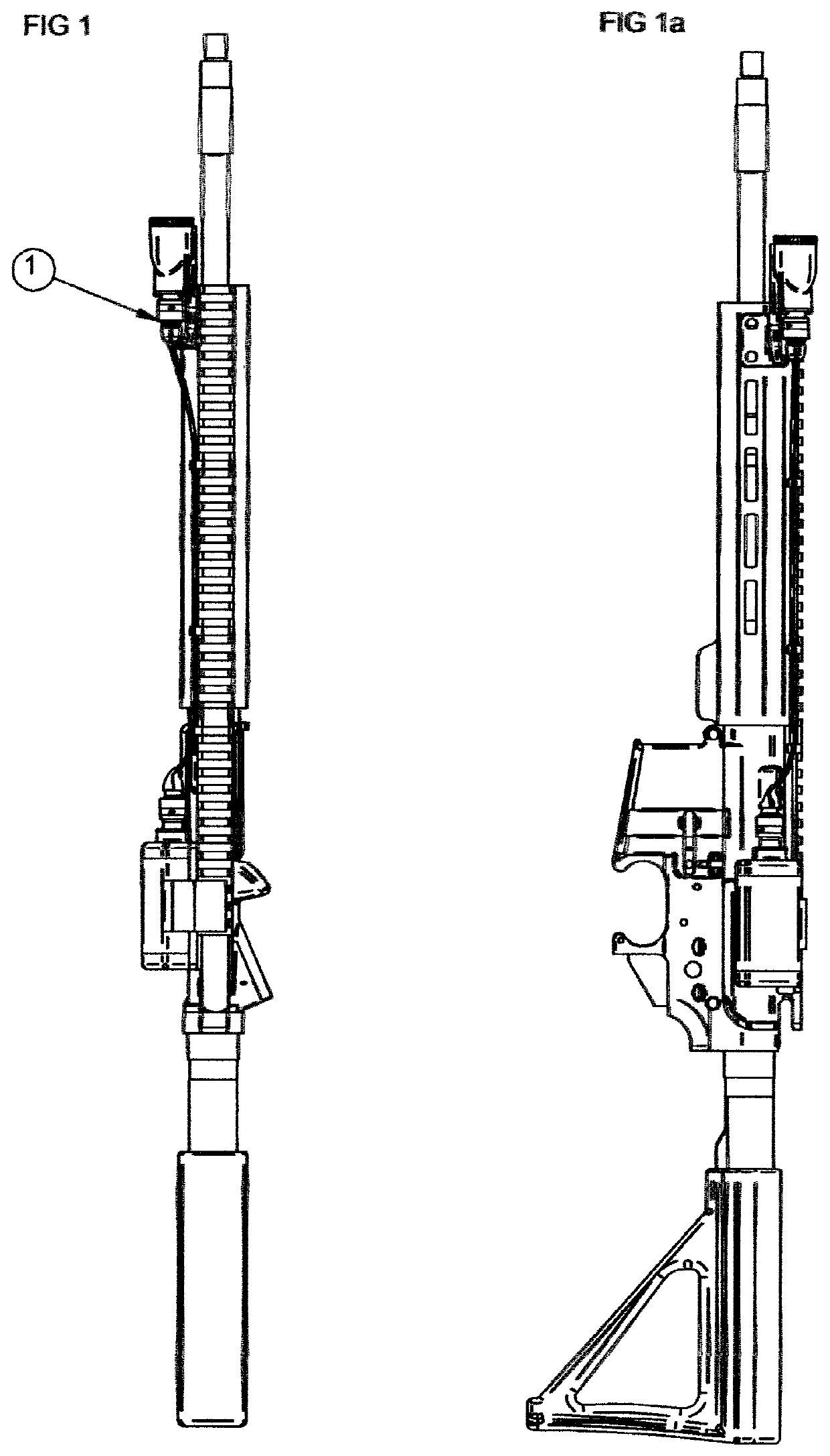
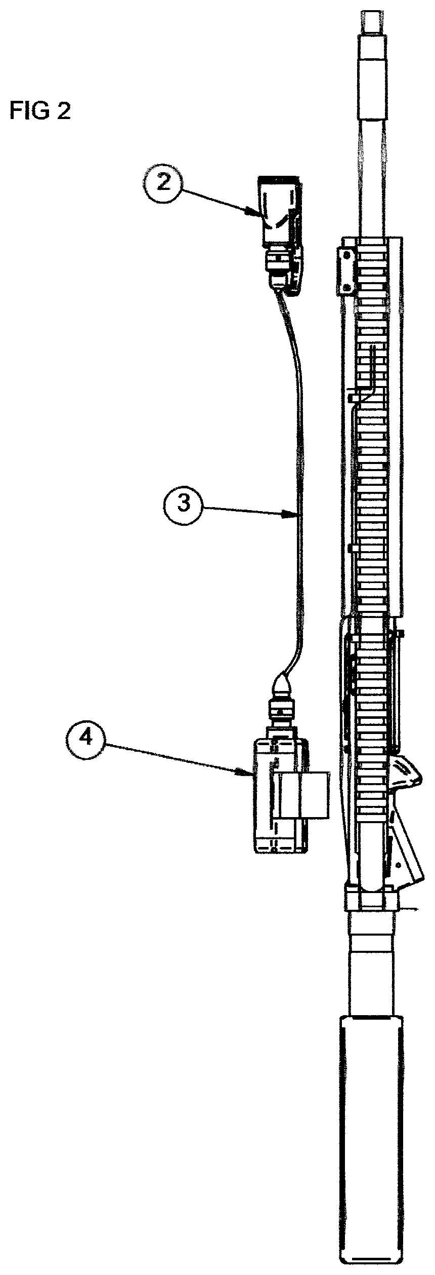
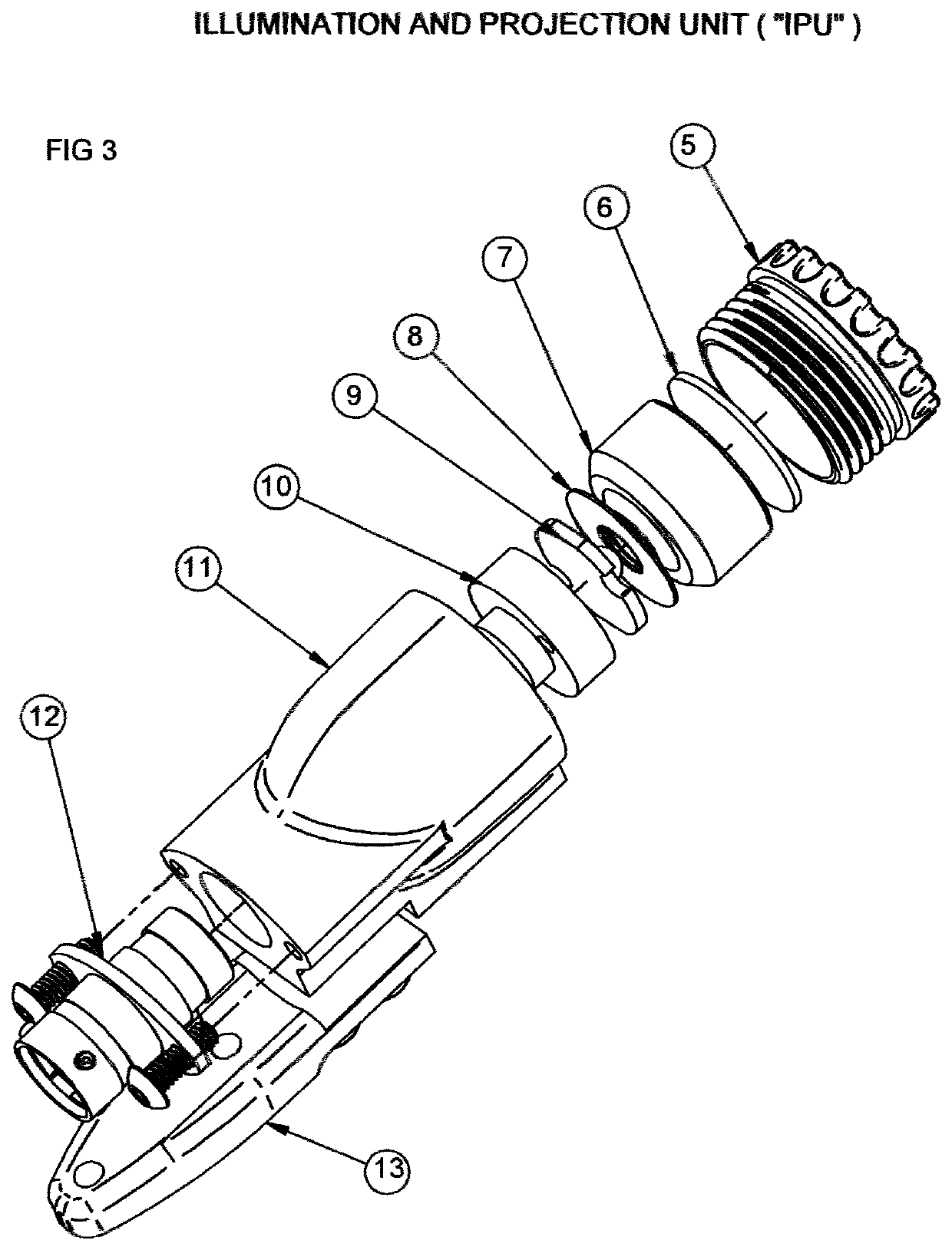
[0013]The embodiments of the invention 1 (complete system) shown mounted to a firearm in FIG. 1 and FIG. 1a, then FIG. 2 showing the Illumination and Projection Unit (IPU) 2, and the connecting wire harness 3, and the Power and Control Unit (PCU) 4 which comprise the major embodiments of this example (understood to be an example, not a limitation in terms of number of embodiments that make up “the system.”) Beginning with the forward (toward muzzle) mounted IPU 2, the exploded view of which is seen in FIG. 3. The IPU consists of a housing 11 of some shape and construction to house the minimally necessary components for illumination and projection. In this example, these components include the threaded lens cap 5, the lens 6, the reflector 7, an insulating washer 8, the LED mounted to a copper plate 9, a heatsink 10. The necessary wiring will connect from the military style connector 12 to the contact points on the LED copper plate. FIG. 3, FIG. 4, FIG. 4a show an example of a relati...


PUM

PropertyMeasurementUnit
electromagnetic spectrumaaaaaaaaaa
energyaaaaaaaaaa
power/energyaaaaaaaaaa

Abstract

This invention herein described is a firearm mountable, illumination and projection system for projecting, detecting and / or receiving electromagnetic radiation (waves) from across the electromagnetic spectrum by utilizing a variety of technologies such as LED's, Infrared Illuminators, Laser Emitters, and FLIR sensors (examples not limitations). This invention, herein described, is unique in that the embodiment(s) for Illumination and Projection are separate, unique, and isolated (distally) from the embodiment providing the necessary power (Current, Voltage, Electromotive Force) for the illumination and / or projection of electromagnetic radiation.

Description

CROSS REFERENCE TO RELATED APPLICATIONS[0001]The present application claims priority benefit to U.S. Provisional Application No. 63 / 067,831 filed on Aug. 19, 2020STATEMENT REGARDING FEDERALLY SPONSORED RESEARCH OR DEVELOPMENT[0002]The invention was not created in conjunction with any federally sponsored program for research or developmentREFERENCE TO A SEQUENCING LIST[0003]Not applicableBACKGROUND OF THE INVENTIONField of Invention[0004]This invention is related to firearm accessories such as mountable flashlights, “tac” lights, infrared illuminators, and laser emitters, and detectors, and other aiming devices that are used with and mounted to firearms.Description of Prior Art[0005]A survey of prior art in this field shows that all firearm mountable flashlights (tac lights) and other devices for lighting, illumination, and projection of electromagnetic radiation (waves) have the power supply (batteries for example) contained within, or directly attached to, the same embodiment (hous...

Claims


Application Information

Patent Timeline
Patent Type & Authority Applications(United States)
IPC IPC(8): F41G1/35
CPCF41G1/35F41G1/36
Inventor LINDBLOM, JR., PETER DORNHINCAPIE, DANIEL
Owner HINCAPIE DANIEL
Why Eureka
Try Eureka