Polishing slurry composition
Pending Publication Date: 2022-03-03
K C TECH
View PDF0 Cites 0 Cited by
- Summary
- Abstract
- Description
- Claims
- Application Information
AI Technical Summary
Benefits of technology
The present patent relates to a polishing slurry composition that can quickly polish silicon oxide films and polysilicon films without leaving any residue after shallow trench isolation polishing of semiconductor devices. Additionally, it can reduce dishing in silicon oxide films and scratches.
Problems solved by technology
As semiconductor devices become more diversified and highly integrated, finer pattern formation techniques are being used, and accordingly a surface structure of semiconductor devices becomes more complicated and a step height of surface films also becomes greater.
Meanwhile, if a polishing selectivity in an STI process excessively increases, an insulating film layer buried in a trench may be excessively polished, which may lead to dishing and a decrease in a characteristic of a device.
In particular, such dishing may result in a step difference between an active region and a field region in an ultra-micronized device, which may have a significant adverse influence on performance and reliability of the device.
Method used
View moreImage
Smart ImageViewing Examples

Examples
example
[0073][Example]
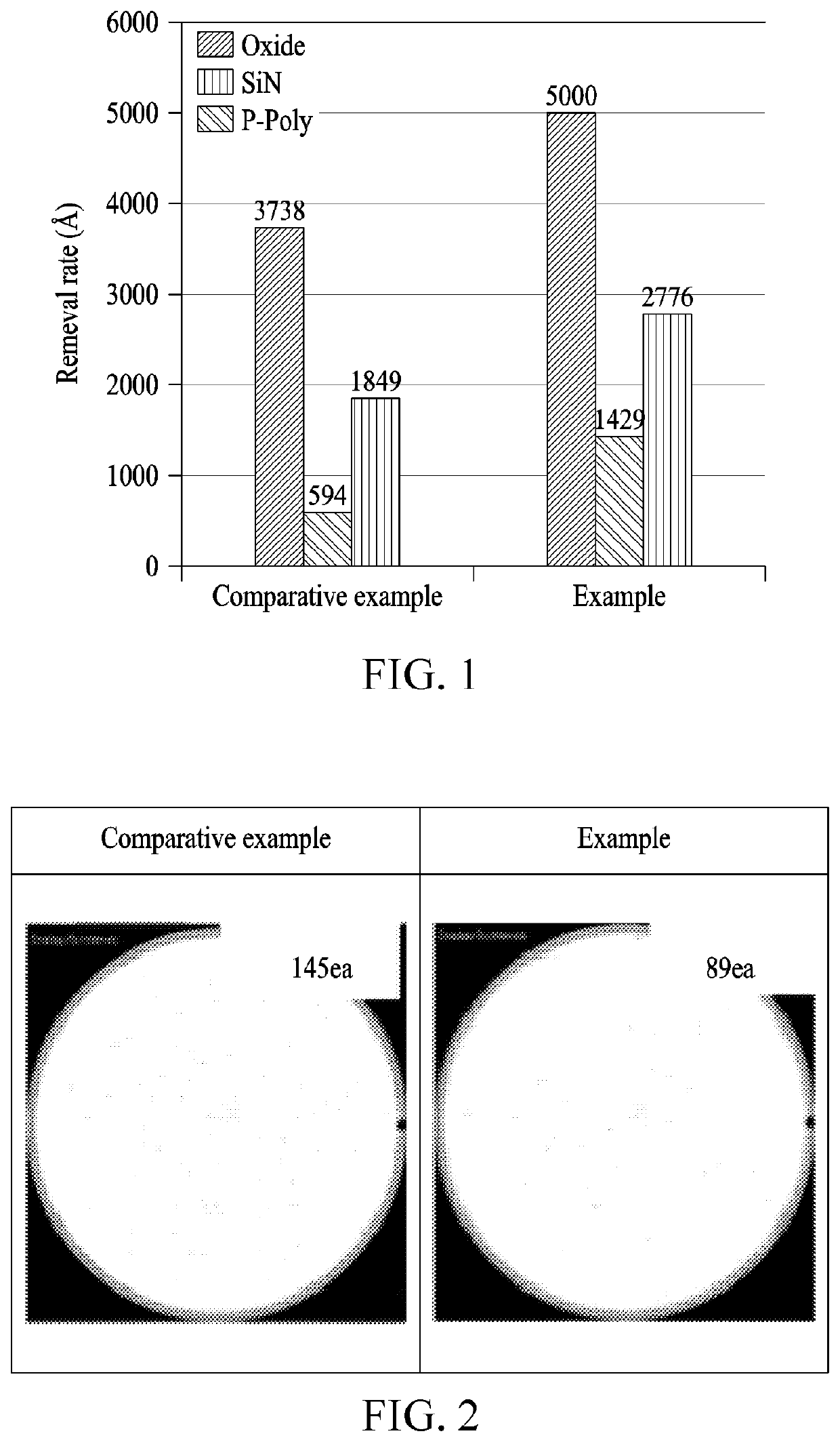
[0074]5 wt % of colloidal ceria particles with a particle size of 60 nm, 0.5 wt % of polyglycerol having a weight-average molecular weight of 750 as a non-ionic (macromolecule) polymer, and 0.25 wt % of picolinic acid as a selectivity control agent were added, to prepare a polishing slurry composition with pH of 4.
Login to View More PUM
 Abstract
The present invention relates to a polishing slurry composition. A polishing slurry composition according to an embodiment of the present disclosure comprises a polishing solution containing polishing particles; and an additive solution containing a non-ionic polymer and a polishing selectivity controller. The polishing slurry composition of the present disclosure has a high polishing rate for silicon oxide films and polysilicon films, leaves no residues after shallow trench isolation (STI) polishing of semiconductor devices, and can reduce the amount of silicon oxide film dishing and decrease scratches.
Description
TECHNICAL FIELD[0001]The present disclosure relates to a polishing slurry composition.BACKGROUND ART[0002]As semiconductor devices become more diversified and highly integrated, finer pattern formation techniques are being used, and accordingly a surface structure of semiconductor devices becomes more complicated and a step height of surface films also becomes greater. A chemical mechanical polishing (CMP) process is used as a planarization technique for removing a stepped portion of a specific film formed on a wafer in manufacturing of a semiconductor device. The CMP process is, for example, a process for removing an insulating film excessively formed for layer insulation, and is widely used as a process for planarizing an interlayer dielectric (ILD) and an insulating film for shallow trench isolation (STI) to insulate chips from each other and as a process for forming a metal conductive film, for example, a wiring, a contact plug, a via contact, and the like.[0003]To protect a pat...
Claims
Login to View More Application Information
Patent Timeline
 IPC IPC(8): C09G1/02C09K3/14H01L21/304C09G1/04
CPCC09G1/02C09K3/1436B82Y40/00C09G1/04H01L21/304H01L21/31053B82Y30/00C09K3/1409C09K3/1463C09K3/1454H01L21/762H01L21/76229
Inventor CHOI, SOO WANKIM, JUNG YOONCHOI, NAK HYUNYANG, HAE WON
Owner K C TECH
Features
- Generate Ideas
- Intellectual Property
- Life Sciences
- Materials
- Tech Scout
- Unparalleled Data Quality
- Higher Quality Content
- 60% Fewer Hallucinations
Learn More Browse by: Latest US Patents, China's latest patents, Technical Efficacy Thesaurus, Application Domain, Technology Topic, Popular Technical Reports.
© 2025 PatSnap. All rights reserved.Legal|Privacy policy|Modern Slavery Act Transparency Statement|Sitemap|About US| Contact US: help@patsnap.com