Rapid compression machine with electrical drive and methods for use thereof

a compression machine and electric drive technology, applied in the direction of engine testing, structural/machine measurement, instruments, etc., can solve the problems that further analysis may not be necessary or desirable, and achieve the effect of increasing pressure and temperature in the reaction chamber and reducing the volume of the reaction chamber

Pending Publication Date: 2022-03-03
UNIVERSITY OF IDAHO
View PDF45 Cites 2 Cited by
  • Summary
  • Abstract
  • Description
  • Claims
  • Application Information

AI Technical Summary

Benefits of technology

[0010]In another representative embodiment, a method can comprise advancing a piston into a chamber housing using an electrical drive. The chamber housing and the piston can together define a reaction chamber. The advancing can reduce a volume of the reaction chamber, thereby increasing pressure and temperature in the reaction chamber. The method can further comprise, after the adva

Problems solved by technology

For example, when the RCM is used to perform an experiment to characterize autoignition

Method used


Image

  • Rapid compression machine with electrical drive and methods for use thereof
  • Rapid compression machine with electrical drive and methods for use thereof
  • Rapid compression machine with electrical drive and methods for use thereof

Examples


example 1

pression-Expansion Machine (RCEM)

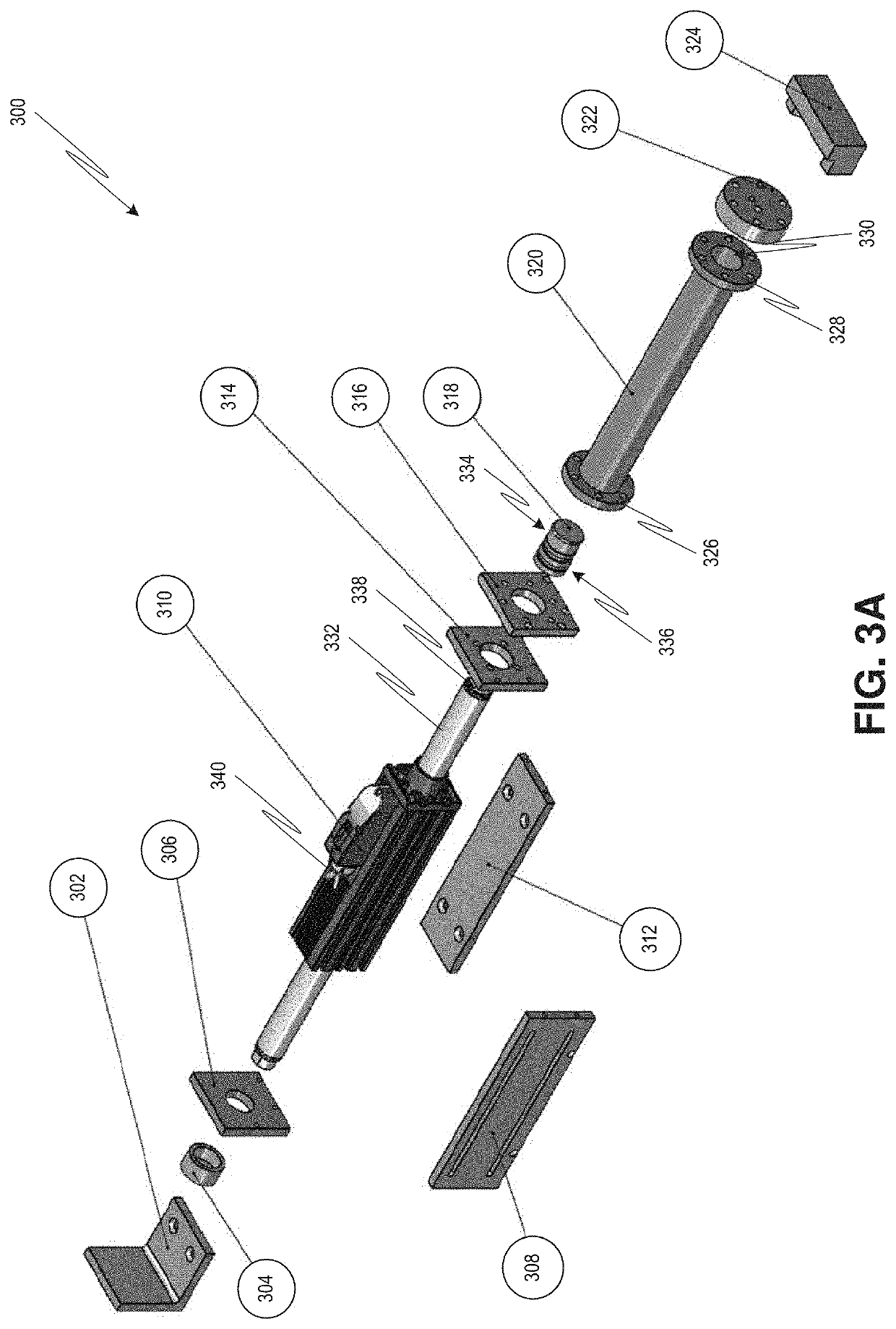
[0089]FIGS. 3A-14D illustrates a fabricated RCEM 300 and components thereof that was used to investigate autoignition, ignition delay times, and induction-period stable intermediaries of n-Heptane. RCEM 300 has a linear actuator 310 (sold by Dunkermotoren GmbH, Bonndorf, Germany) that drives a thrust rod 332 (e.g., formed of stainless steel) with enclosed rare earth magnets in a linear fashion. The linear actuator 310 has therein a plurality of motor coils (e.g., stator coils) as well as position sensing electronics (e.g., integrated encoder). An electrical connector 340 on the linear actuator 310 is used to provide electrical power thereto as well as to provide communication between the linear actuator 310 and a control system (e.g., control system 114 in FIG. 1). The thrust rod 332 has a threaded end 338 that screws into a mounting hole 420 (see FIG. 4B) at a rear face 418 of piston 318 (e.g., formed of aluminum). The thrust rod 332 and piston 318 ...

example 2a

on of n-Heptane

[0100]Using a fabricated RCEM, the autoignition of n-Heptane was studied. A premixed test charge was prepared in a 12.41 L stainless steel vessel equipped with magnetic stirrers. The oxidizer was comprised of ultra-high purity argon and oxygen in a molar ratio of 1:3.76. The composition of the oxidizer was determined based on the fill pressure for each individual component, and an appropriate amount of liquid fuel (n-Heptane ≥99%) was weighed and injected into the mixing tank. This mixture was then introduced into the RCEM for the tests. The piston rapidly compresses the fixed mass of gas from an initial state (T0, P0) to a final compressed state (Pc, TC). A data acquisition device (NI PCIe-6351, X Series DAQ with 16 analog inputs, 24 digital inputs / outputs, and 2 analog outputs; sold by National Instruments, Austin, Tex.) was used to acquire pressure and encoder pulse data shown in FIGS. 15A and 15B.

[0101]As discussed above, the fabricated RCEM can operate with just ...

example 2b

elay Times

[0104]Using the fabricated RCEM, results were obtained for autoignition of n-Heptane at a compressed charge pressure (PC) of 5 bar and for compressed temperatures (TC) in a range of 600-750 K. Selected pressure traces for an equivalence ratio of ϕ=0.25 are shown in FIG. 17A, with the pressure trace corresponding to TC=600 labeled as 1704 and the pressure trace corresponding to TC=632K labeled as 1702. As shown in FIG. 17A, there is a clear two-stage ignition trend in the pressure-time records. FIG. 17B shows the first-stage delay 1706 and the overall ignition delay 1708 inferred from the pressure traces of FIG. 17A as a function of temperature. The overall ignition delay 1708 was seen to exhibit a negative temperature coefficient behavior while the first stage delay 1706 decreases monotonically with increasing temperature. FIGS. 17A-17B also show that the fabricated RCEM provided relatively-long ignition delay times of up to a quarter-second (250 ms). Such long delay times...


PUM


Abstract

A rapid compression machine (RCM) employs an electrical drive to move a piston disposed within a chamber housing. The electrical drive converts electrical power into linear motion of the piston, for example, to compress contents in a reaction chamber defined by the chamber housing and the piston. The temperature and pressure changes induced by the compression can cause reaction of contents within the chamber, for example, autoignition of the contents. The RCM can thus be used to study chemical kinetics. In some embodiments, the electrical drive can also rapidly move the piston in reverse to expand a volume of the reaction chamber, for example, to quench the compression-induced reaction therein. In such embodiments, the RCM may be considered a rapid compression-expansion machine (RCEM) and can be used for speciation studies.

Description

CROSS REFERENCE TO RELATED APPLICATION[0001]This application claims the benefit of U.S. Provisional Application No. 63 / 070,935, filed Aug. 27, 2020, which is incorporated herein by reference in its entirety.FIELD[0002]The present disclosure relates generally to systems and methods for performing chemical studies, and more particularly, to rapid compression machines and methods for use thereof.BACKGROUND[0003]Rapid compression machines (RCMs) have been used to study chemical kinetics. RCMs can simulate a single compression stroke of an internal combustion (IC) engine. However, unlike an IC engine, RCMs are designed to minimize fluid dynamic effects of in-cylinder charge motion in order to provide an aerodynamically-clean environment where chemical kinetics can be studied, in particular, fuel-combustion kinetics. For example, RCMs have been used to study the chemistries and autoignition behaviors of alkanes, cycloalkanes, aromatics, alcohols, gasoline, diesel fuel, and jet-fuel, among...

Claims


Application Information

Patent Timeline
IPC IPC(8): G01M15/08G01M15/02G01M15/04
CPCG01M15/08G01M15/048G01M15/02G01M15/06
Inventor KUMAR, KAMAL
Owner UNIVERSITY OF IDAHO
Why Eureka
Try Eureka