Multi-use beam sampler in laser beam delivery path of ophthalmic laser system

a laser system and laser beam technology, applied in the direction of photometry using electric radiation detectors, optical radiation measurement, instruments, etc., can solve the problems of system substantially obviating one or more of the problems, significant etc., to reduce alignment complexity, reduce optical losses and wavefront distortion, and simplify the effect of structur

Pending Publication Date: 2022-03-24
AMO DEVMENT
View PDF0 Cites 0 Cited by
  • Summary
  • Abstract
  • Description
  • Claims
  • Application Information

AI Technical Summary

Benefits of technology

[0007]An object of the present invention is to provide a laser beam delivery system that has a simpler structure, reduced alignment complexity, and reduced optical losses and wavefront distortion.

Problems solved by technology

In an ophthalmic laser system which require three sampled beams to be formed (two for the separate laser energy monitoring detectors and one for the depth measurement detector), to use three separate beam samplers in the main laser beam path would result in significant optical losses and wavefront distortion.
Such a system substantially obviates one or more of the problems due to limitations and disadvantages of the related art.

Method used


Image

  • Multi-use beam sampler in laser beam delivery path of ophthalmic laser system
  • Multi-use beam sampler in laser beam delivery path of ophthalmic laser system

Examples


Embodiment Construction

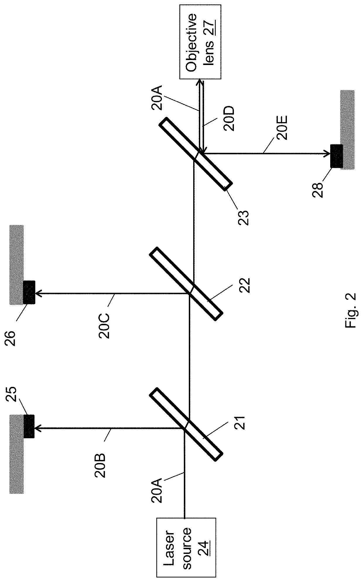
[0015]FIG. 2 schematically illustrates a laser beam delivery system for an ophthalmic laser surgical system which employs three separate beam samplers 21, 22 and 23. As shown in FIG. 2, the laser beam 20A generated by a laser source 24 sequentially passes through the first, second and third beam samplers 21, 22 and 23. Fractions 20B and 20C of the beam are reflected at the front surfaces of the first and second beam samplers 21 and 22, respectively, toward two independent energy monitoring detectors (i.e. photodiodes) 25 and 26, respectively. Detectors 25 and 26 provide redundant energy monitoring functions. After passing through the third beam sampler 23 (the reflection from this beam sampler is not shown), the laser beam 20A is focused by an objective lens 27 to the target (e.g. the eye, or a patient interface device, or other target, not shown in FIG. 2). The laser beam reflected and / or scattered from the target is collected by the objective lens as the return beam 20D, a fractio...


PUM


Abstract

In a laser beam delivery system for an ophthalmic laser system, a single multi-use beam sampler is employed to form three sampled laser beams, including two for redundant laser energy monitoring and one for laser focal point depth measurement. The beam sampler is a transparent plate with preferably parallel front and back surfaces. The front surface reflects a fraction of the incoming beam to form the first sampled beam toward an energy monitoring detector. The back surface reflects another fraction of the beam to form a second sampled beam exiting backwardly from the front surface toward another energy monitoring detector. An objective lens focuses the transmitted beam onto a target, and collects back reflected or scattered light from the target to form a return beam. The back surface of the beam sampler reflects a fraction of the return beam to form the third sampled beam toward a third detector.

Description

CROSS-REFERENCE TO RELATED APPLICATIONS[0001]This application claims the benefit under 35 U.S.C. § 119(e) of U.S. Provisional Patent Application No. 63 / 081,081, filed Sep. 21, 2020, which is incorporated herein by reference in its entirety.BACKGROUND OF THE INVENTIONField of the Invention[0002]This invention relates to ophthalmic laser surgical systems, and in particular, it relates to a laser beam delivery system for an ophthalmic laser surgical system.Description of Related Art[0003]In ophthalmic laser surgical systems, to meet relevant safety requirements, the energy monitoring component must function in a redundant way to monitor the laser power delivered to the surgical target. In a typical ophthalmic laser surgical system, small fractions of the laser beams are picked at two places and sent towards two independent detectors to monitor the laser energy or power.[0004]In some ophthalmic laser surgical systems, a beam splitter is used to direct a small fraction of the return lase...

Claims


Application Information

Patent Timeline
Patent Type & Authority Applications(United States)
IPC IPC(8): A61F9/008G02B26/08G02B27/10G01J1/42
CPCA61F9/008G02B26/0875A61B2018/20553G01J1/4257G02B27/108A61F9/0084A61F9/00814
Inventor RAHAMAN, MOHAMMAD SAIDURFU, HONG
Owner AMO DEVMENT
Why Eureka
Try Eureka