Waste Gas Combustor

a combustor and waste gas technology, applied in the field of combustor, can solve the problems of environmental regulations, simple venting of waste gas to the atmosphere, and environmental hazards, and achieve the effect of reducing the length, diameter and cost of the piping

Pending Publication Date: 2022-03-31
CLEAR RUSH CORP
View PDF4 Cites 0 Cited by
  • Summary
  • Abstract
  • Description
  • Claims
  • Application Information

AI Technical Summary

Benefits of technology

[0007]A combustor having a rectangular prism structure, enclosed on a bottom surface and 4 sidewalls thereof with a top side left open for heat and combustion by-products to exit therefrom, can be provided with a burner assembly mounted inside for burning waste gas with combustion air provided through flame arrestors from outside atmospheric air. The combustor can comprise a controller, configured as a burner management system, for operating an igniter disposed on the burner assembly, and can further comprise thermocouples for measuring the temperature of exhaust gas exiting the combustor and for measuring the skin temperature of the structure wherein the thermocouples can provide temperature information to the controller for controlling the operation of the combustor. In some embodiments, the combination of the burner management system, the flame arrestors and the thermocouples can allow the combustor to be placed as close as 10 meters to a well or gas venting equipment as the burner management system can be configured to monitor the exhaust temperature and the skin temperature of the combustor and control the rate of combustion of waste gas to keep those temperatures from exceeding the auto-ignition temperature of the waste gases. By reducing the distance, the combustor can be placed near a well or venting equipment, this reduces the length, diameter and cost of the piping required to supply waste gas to the combustor.
[0008]In some embodiments, the combustor can comprise a square base that can be lifted and transported by a forklift. In some embodiments, the combustor can further comprise rectangular sidewalls wherein the resulting combustor can be easily placed at a well site or near venting equipment without having a cement pad placed first; the combustor can be placed directly onto the ground and not require additional stabilization with guy wires and the like. By eliminating the need of a cement pad, the time and cost to place the combustor near a well site or venting equipment can be reduced.
[0009]In some embodiments, the square base can be nominally 60 inches on a side and the sidewalls can be nominally 120 inches tall. In such configurations, 7 to 8 units of the combustor can be transported on a flat deck trailer or B-train trailer. This can reduce the cost of transportation and logistics of moving the combustor to and from sites as compared to prior art combustors.
[0010]In some embodiments, the combustor can be used to safely dispose of waste hydrocarbon gases produced from oil and gas production activities, agricultural activities and from municipal landfills, waste management systems and sewage systems.
[0011]In some embodiments, the combustor can come equipped with a burner management system, valve train and flow meter. The flow meter can measure the gas flow being burnt in the combustor that, in turn, can send data to the burner management system that can operate as a supervisory control and data acquisition (“SCADA”) system that can control data coming acquired about the GHGs being combusted. In some embodiments, the burner management system can wirelessly transmit the data using a cellular transceiver device over a telecommunications network such as through the public switched telephone network (“PSTN”). This cellular device can then send the raw data to a central monitoring system for a geographic region where the central monitoring system can comprise a software platform that can store data received from a particular combustor. In some embodiments, the burner management system can safely light the combustor and monitor temperatures therein as well as providing visual indications of the temperatures for the operators to read.
[0012]The combination of the burner management system and the cellular unit can provide flow value and temperature data in addition to operation data as to whether the combustor is operating or not as well as the location of the combustor. Operators can be notified through the software program as to whether the combustors are running and to their whereabouts so they know where to go to check on them and get them up and running again in the event the combustor ceases to operate. By operating combustors using the systems and methods described herein, operators can maximize the operating time of their combustors with minimal manpower given that the status and operation of every combustor can be monitored by the central control center. In addition, the central control center can accurately monitor the volume of waste gas burned by each combustor thereby ensuring the operator can accurately track the amount of carbon credits they can acquire from the volume of waste burned from each combustor. This enables operators to maximize the carbon credits they are able to earn from the waste gas being combusted by the combustor.

Problems solved by technology

Combusting the waste gas is the environmentally friendly method of disposing of the waste gas as allowing the waste gas to vent to the atmosphere can be an environmental hazard as it can add to and worsen the effect of greenhouse gases (“GHGs”) in the atmosphere.
Simply venting waste gas to the atmosphere is also contrary to environmental regulations in many jurisdictions.
Prior art combustors are typically a vertically oriented cylindrical structure that are difficult to transport and to install at a site.
Due to their configuration, transporting prior art combustors is difficult and a typical truck trailer is limited to carrying only two to three prior art combustors at a time, which increases transportation and logistics costs in moving such combustor to and from well sites and venting equipment.
The requirement of placing cement pads and the use of guy wires for stabilization increases both the time and cost to place prior art combustors.
A problem arising from this, however, is the ability to monitor and collect of data relating to the amount and type of GHGs that are burned off.
It is possible to manually monitor the amount of GHGs combusted but doing so can be prone to errors and inaccuracies and may result in the operator not acquiring all the carbon credits they may be entitled to.
Combustors can also be located in remote and often difficult places to reach, which makes accurate collection of data of GHG combustion more difficult.

Method used


Image

  • Waste Gas Combustor
  • Waste Gas Combustor
  • Waste Gas Combustor

Examples


Embodiment Construction

[0055]In this description, references to “one embodiment”, “an embodiment”, or “embodiments” mean that the feature or features being referred to are included in at least one embodiment of the technology. Separate references to “one embodiment”, “an embodiment”, or “embodiments” in this description do not necessarily refer to the same embodiment and are also not mutually exclusive unless so stated and / or except as will be readily apparent to those skilled in the art from the description. For example, a feature, structure, act, etc. described in one embodiment can also be included in other embodiments but is not necessarily included. Thus, the present technology can include a variety of combinations and / or integrations of the embodiments described herein.

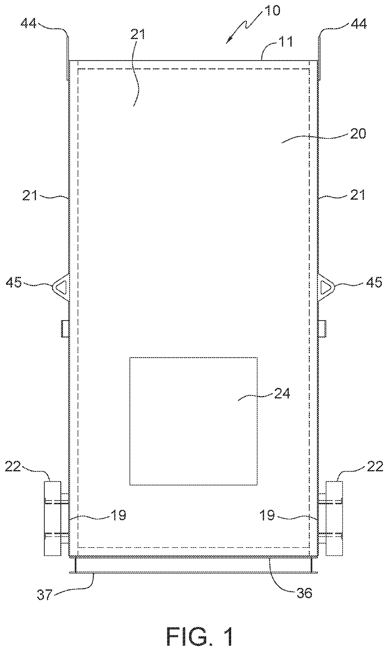
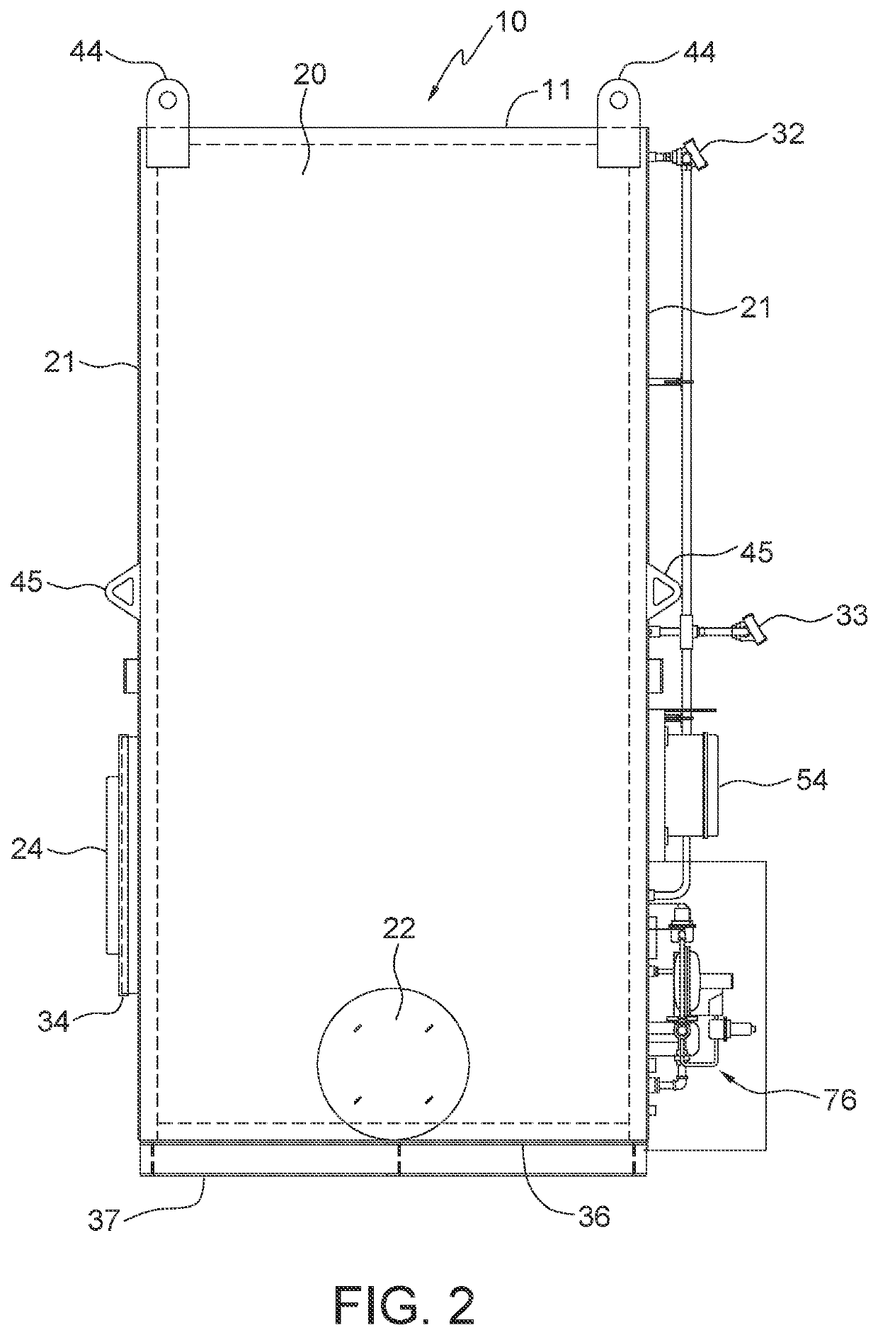
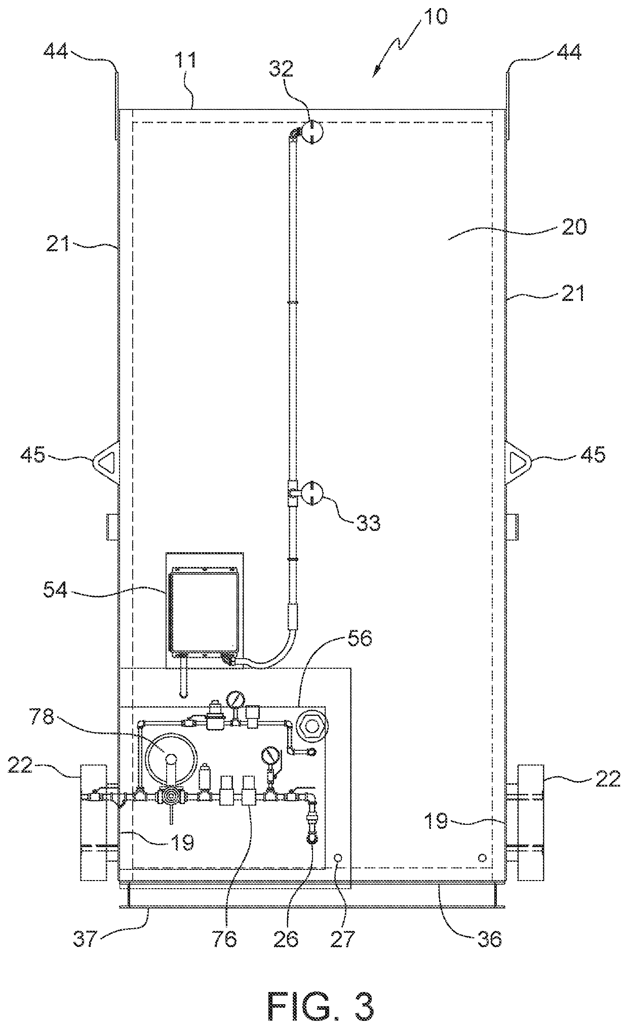
[0056]Referring to the Figures, an embodiment of an improved combustor 10 is shown. Referring to FIGS. 1 to 6, a first embodiment of combustor 10 is shown, which can further comprise of base box 20 that can comprise of base plate 36 a...


PUM


Abstract

A combustor having a rectangular prism structure with a burner assembly mounted inside for burning waste hydrocarbon gases with combustion air provided through flame arrestors from outside atmospheric air, the combusted hydrocarbon gas exiting through an opening on top of the structure. The combustor includes a controller for operating an igniter on the burner assembly and thermocouples for measuring the temperature of exhaust gas exiting the combustor and for measuring the skin temperature of the structure. The controller can relay the operational data and the location of the combustor to a central control center through a SCADA unit connected to a telecommunications network. The controller can also relay the volume of waste gas burned to the central control center to determine the carbon credits earned by preventing the waste gas being vented to the atmosphere.

Description

PRIORITY STATEMENT & CROSS-REFERENCE TO RELATED APPLICATIONS[0001]This application claims priority from co-pending U.S. Patent Application Ser. No. 63 / 084,687 entitled “Waste Gas Combustor” and filed on Sep. 29, 2020, in the names of Christopher Lucien Aldrich, et al.; which is hereby incorporated by reference, in entirety, for all purposes.TECHNICAL FIELD OF THE INVENTION[0002]The present disclosure is related to the field of combustors, in particular, combustors for eliminating low pressure and low volume waste gas from hydrocarbon producing wells and hydrocarbon production facilities in addition to hydrocarbon gases produced from agricultural activities and from municipal landfills, waste management systems and sewage systems.BACKGROUND OF THE INVENTION[0003]Combustors can be used for burning off or combusting waste gas from a hydrocarbon producing well or hydrocarbon production facilities where the waste gas is of too low a pressure or volume, or both, to be of any use as a down...

Claims


Application Information

Patent Timeline
Patent Type & Authority Applications(United States)
IPC IPC(8): F23G7/08F23D14/82F23G5/50F23L1/02
CPCF23G7/085F23D14/82F23G2207/101F23L1/02F23G2209/14F23G5/50F23G7/06
Inventor ALDRICH, CHRISTOPHER LUCIENALDRICH, DALE CHRISTOPHERROSEVEAR, DALLAS LANE
Owner CLEAR RUSH CORP
Why Eureka
Try Eureka