
Busbar assembly with alignment and touch-proof features for network elements

a technology of network elements and assembly parts, applied in the direction of support structure mounting, electrical equipment, servers, etc., can solve the problems of increasing power densities within new network communication systems, power demand too high for power planes, and power distribution in shelf-mounted equipmen

Active Publication Date: 2022-04-14
CIENA
View PDF0 Cites 0 Cited by
  • Summary
  • Abstract
  • Description
  • Claims
  • Application Information

AI Technical Summary

Benefits of technology

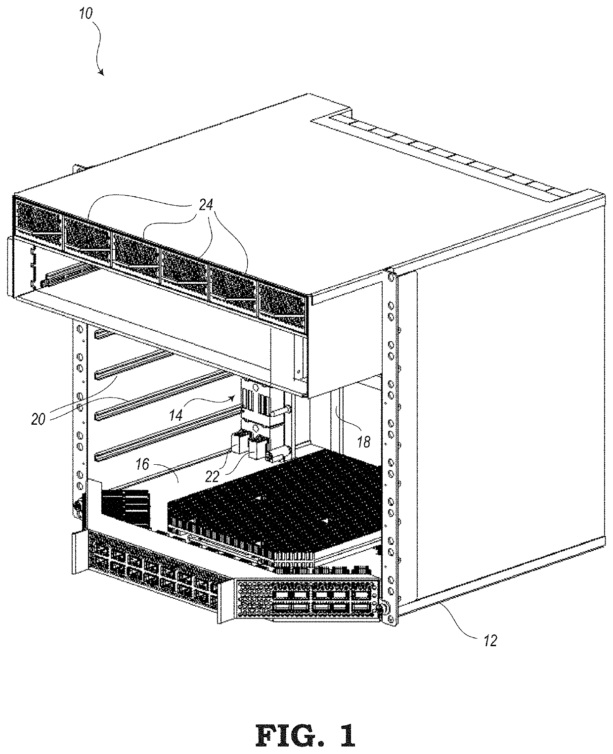
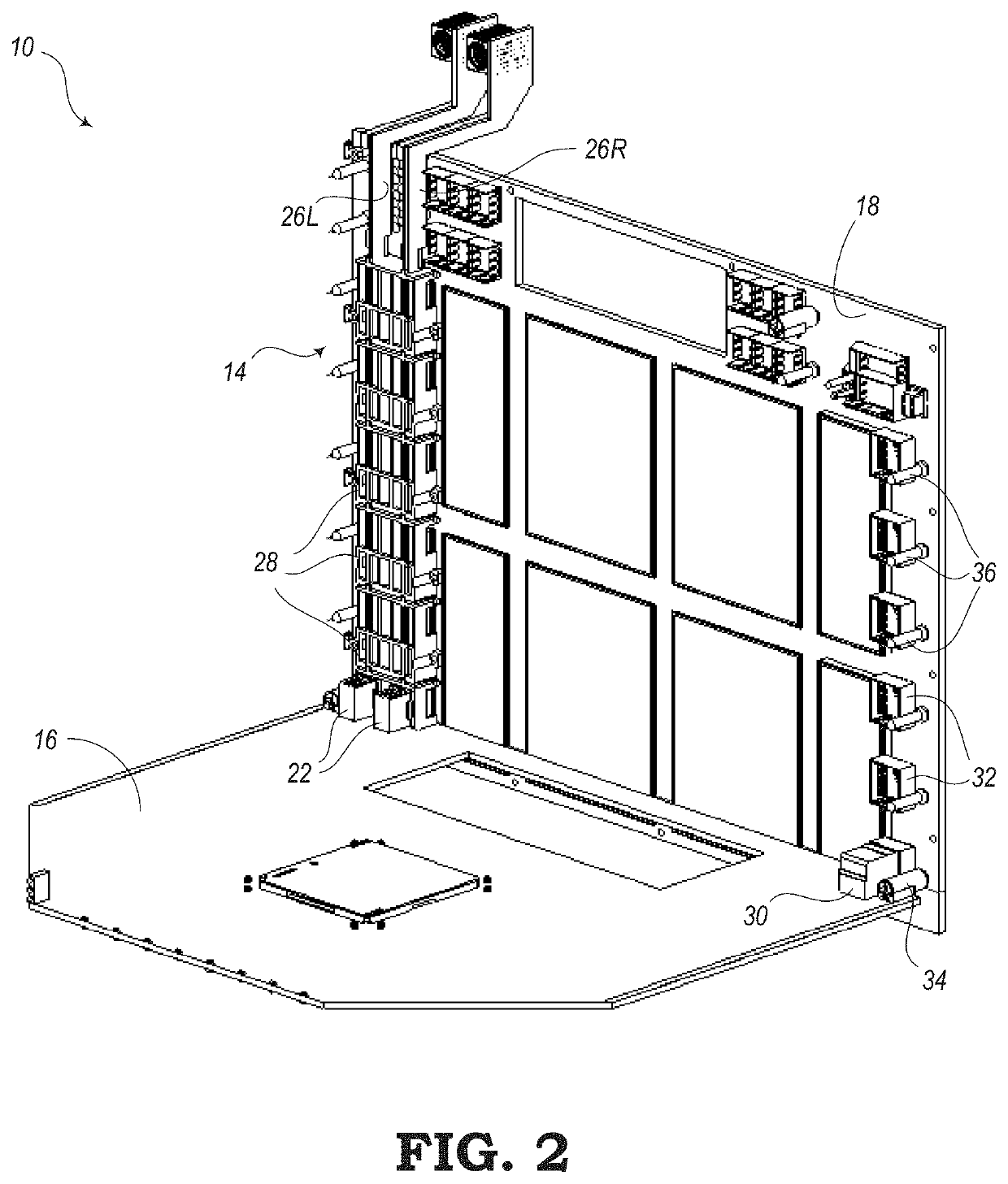
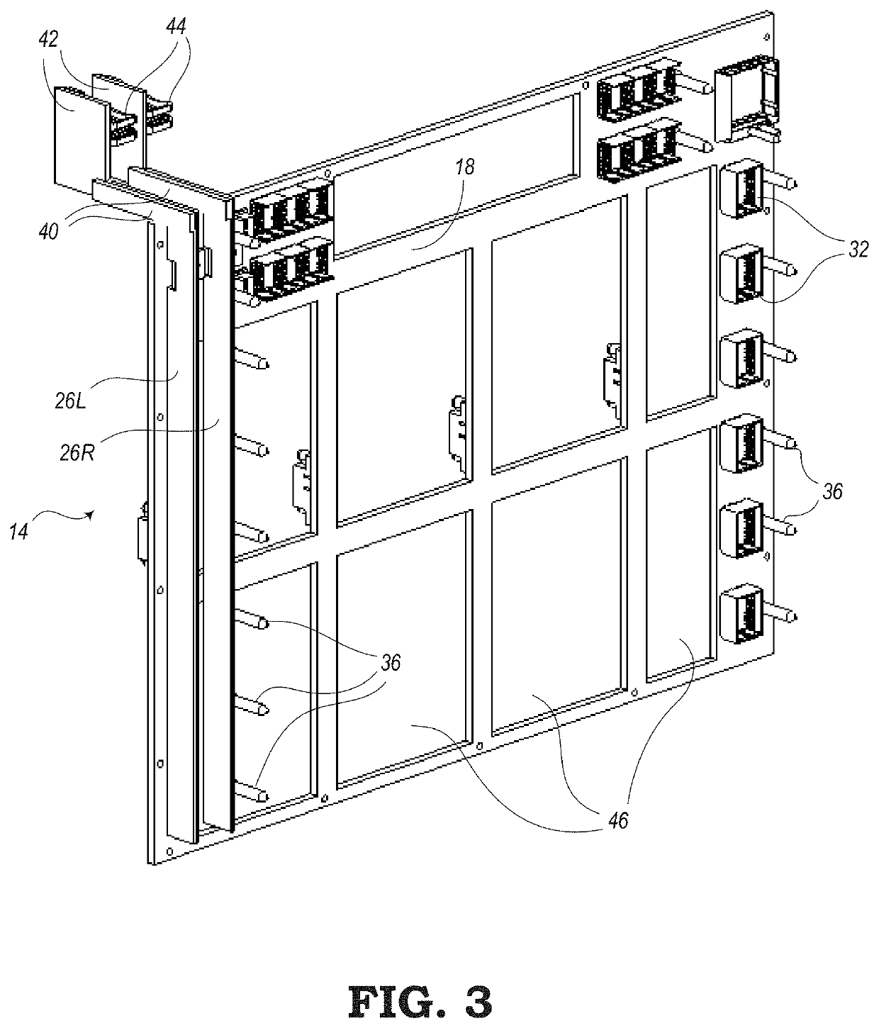
The present patent is directed to systems for carrying electrical power from a power source to a circuit board. These systems include busbar assemblies that are arranged on a front face of a non-conductive substrate, such as a backplane or midplane of a shelf or cabinet that houses networking equipment. The busbar assembly includes a pair of conductive busbar strips that are held in place by non-conductive modules to align the busbar strips and reduce the risk of electric shock. A protective module is also described that provides tight alignment of the conductive vertical strips with respect to the non-conductive vertical substrate and simultaneous blind mating of power connections and signal connections. The technical effects of the present patent include efficient and safe transfer of power from power sources to circuit boards.

Problems solved by technology

In addition to a more compact form, power demands are also increasing, which results in greater power densities within new generations of network communication systems.
Also, power distribution in shelf-mounted equipment is an issue that must be addressed in this environment.
As demands continue to increase with respect to size and electrical power, the power demands have become too high to run power planes within a power structure of a backplane circuit board.
Also, beyond a certain point, it is no longer practical to keep adding layers to a circuit board substrate (e.g., midplane) to increase its power carrying capacity.
These floating power cables (e.g., six-gauge wires or greater) may be quite large and take up a significant amount of space.
Therefore, with this conventional power supply system, it becomes difficult to utilize these large power supply components within more recently developed shelf systems having a more compact size.
With shelves becoming more compact and with power increasing, the greater power densities in smaller spaces can produce large amounts of heat that needs to be removed from the system to keep temperatures at proper levels.

Method used


Image

  • Busbar assembly with alignment and touch-proof features for network elements
  • Busbar assembly with alignment and touch-proof features for network elements
  • Busbar assembly with alignment and touch-proof features for network elements

Examples


first embodiment

[0061]FIGS. 8-11 shows various views of an alignment block 60, which may be representative of one of the alignment blocks 28, 28a shown in FIGS. 4-7. FIG. 8 is a front perspective view of the alignment block 60 and FIG. 9 is a back perspective view of the alignment block 60. FIG. 10 is a front view and FIG. 11 is back view of the alignment block 60.

[0062]The alignment block 60 may be configured to provide alignment for power connectors (e.g., power connectors 22) on a circuit board (e.g., circuit board 16) to guide electrical contacts of the power connectors through slots in the alignment block 60 to allow the electrical contacts to be electrically engaged with the conductive strips 26 for providing power to the circuit board. In addition to alignment functions, the alignment block 60 may be configured to provide protective functions for protecting users from electrical shock (or electrocution) from the electrical power being carried by the conductive strips 26 of the busbar system ...

third embodiment

[0084]FIG. 20 is a close-up front perspective view of the third busbar assembly 170 shown in FIG. 19 to show details of the alignment blocks 174 according to a Again, the power connectors 178 of the circuit board 176 are shown as being fully installed in order to connect to the busbars (e.g., conductive strips 172L, 172R). Electrical contact is made through one of the alignment blocks 174 when the circuit board 176 is fully inserted onto the non-conductive substrate 182 for power and signal connection. FIG. 21 shows a front view of the alignment blocks 174 of the busbar assembly 170 shown in FIG. 19 accurately attached to the non-conductive substrate 182.

[0085]FIG. 22 is a front perspective view of one of the alignment blocks 174 shown in FIG. 19 and FIG. 23 is a back perspective view of the alignment block 174. As mentioned above, the alignment block 174 may be configured to provide alignment for power connectors 178 on a circuit board 176 to guide electrical contacts of the power...


PUM


Abstract

Power supply systems are provided for carrying electrical power from a power source to a circuit board mounted on a housing, shelf, cabinet, etc. for supporting networking equipment. A busbar assembly, according to one embodiment, includes a pair of conductive strips configured to carry electrical power. The pair of conductive strips are arranged on a front-facing surface of a non-conductive vertical substrate. The busbar assembly further includes one or more alignment blocks configured to hold the pair of conductive strips in a fixed position with respect to the non-conductive vertical substrate. Each of the one or more alignment blocks is configured to guide a pair of power connectors of a circuit board for making electrical contact with the pair of conductive strips, while allowing simultaneous mating of signal connectors on the circuit board with signal connectors on the substrate, when the circuit board is being installed in a housing.

Description

TECHNICAL FIELD[0001]The present disclosure generally relates to busbar assemblies for providing electrical power to communications equipment. More particularly, the present disclosure relates to a busbar assembly with an alignment mechanism for aligning a circuit board with a pair of conductive busbar strips and a touch-proof mechanism for reducing the risk of electrical shock.BACKGROUND[0002]Communication systems (e.g., optical networking devices, data networking devices, wireless networking devices, storage devices, compute devices, and generally any type of processing equipment that may be deployed in Data Centers, Central Offices, and the like) are typically mounted on a shelf or rack structure. Typically, these shelves might have a depth of about one meter or more. However, as the need for more compact equipment arises, some shelf systems have been created with a depth that is about half (e.g., 600 mm) of conventional shelves. In addition to a more compact form, power demands ...

Claims


Application Information

Patent Timeline
Patent Type & Authority Applications(United States)
IPC IPC(8): H02G5/04
CPCH02G5/04H05K7/1457H05K7/1492H05K7/1454
Inventor SHEARMAN, SIMON J.COSMAN, LLOYD
Owner CIENA
Learn More