Photovoltaic devices comprising luminescent solar concentrators and perovskite-based photovoltaic cells
What is AI technical title?
AI technical title is built by Patsnap AI team. It summarizes the technical point description of the patent document.
a technology of photovoltaic cells and solar concentrators, which is applied in the direction of light-sensitive devices, solid-state devices, electrolytic capacitors, etc., to achieve the effect of improving adhesion
Pending Publication Date: 2022-04-21
ENI SPA
View PDF2 Cites 0 Cited by
Summary
Abstract
Description
Claims
Application Information
AI Technical Summary
This helps you quickly interpret patents by identifying the three key elements:
Problems solved by technology
Method used
Benefits of technology
Benefits of technology
This patent describes a method for improving the efficiency of solar cells by using a scaffold made of mesoporous titanium dioxide. This scaffold increases the area of interface between the perovskite and titanium dioxide, reducing the likelihood of recombination and facilitating the absorption of radiation. The scaffold also acts as an optical path, allowing for longer absorption of radiation. Additionally, the patent suggests using an optical gel to improve adhesion between the perovskite-based solar cell and the luminescent solar concentrator. This method can enhance the conversion efficiency of solar cells and improve their overall performance.
Problems solved by technology
The Applicant therefore posed the problem of discovering a photovoltaic device (or solar device) comprising luminescent solar concentrators (LSCs) and perovskite-based photovoltaic cell cells (or solar cells) that are capable of exhibiting good values of electrical power density (□) and, consequently, good performances.
Method used
Image
Click on the blue label to locate the original text in one second.
Reading with bidirectional positioning of images and text.
[0077]In a 4-litre flask were heated, with magnetic stirring, 2500 ml of methyl methacrylate (MMA) (Sigma-Aldrich), previously distilled in order to remove any inhibitors of polymerisation, bringing the temperature to 80° C., in 2 hours. The following were then added: 250 mg 2,2′-azo-bis[2-methylpropionamidine]dihydrochloride (AIBN) (initiator) dissolved in 250 ml of methyl methacrylate (MMA) (Sigma-Aldrich), previously distilled: the temperature of the mixture obtained falls by approximately 3° C.-4° C. Said mixture was heated, bringing the temperature to 94° C. in 1 hour: all this was left at said temperature for 2 minutes and then cooled in an ice bath, obtaining a pre-polymer syrup which, if not used immediately, may be stored for a few weeks in a refrigerator.
[0078]A mould was then prepared, assembled with two glass plates of dimensions 100×400×6 mm, separated by a seal in polyvinyl chloride (PVC) of larger diameter equal to 6 mm, held tog...
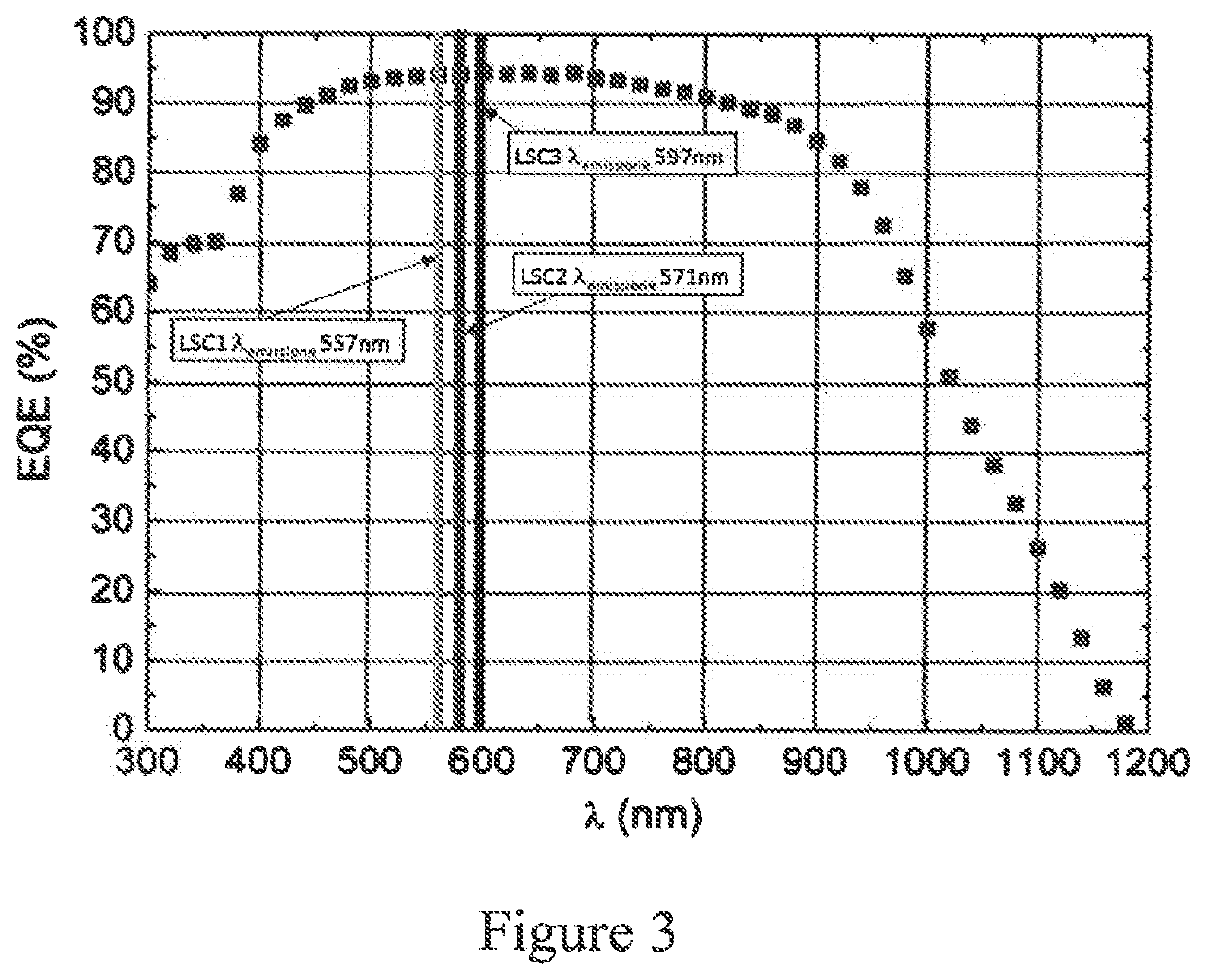
[0080]Plate 2 (LSC2) was prepared by working as reported in Example 1, apart from the fact that instead of 5,6-diphenoxy-4,7-bis[5-(2,6-dimethylphenyl)-2-thienyl]benzo[c]1,2,5-thiadiazole (MPDTBOP), 5,6-diphenoxy-4,7-bis[5-(2,5-dimethylphenyl)-2-thienyl]benzo[c]1,2,5-thiadiazole (PPDTBOP) was used in a quantity equal to 200 ppm, obtaining plate 2 (LSC2) (dimensions 75×300×6 mm).
[0081]Plate 3 (LSC3) was prepared by working as reported in Example 1, apart from the fact that instead of 5,6-diphenoxy-4,7-bis[5-(2,6-dimethylphenyl)-2-thienyl]benzo[c]1,2,5-thiadiazole (MPDTBOP), N,N′-bis(2′,6′-di-iso-propylphenyl)(1,6,7,12-tetraphenoxy)(3,4,9,10-perilene diimide (Lumogen® F Red 305—Basf) was used in a quantity equal to 160 ppm, obtaining plate 3 (LSC3) (dimensions 75×300×6 mm).
PUM
Property
Measurement
Unit
Tg
aaaaa
aaaaa
thickness
aaaaa
aaaaa
Voc
aaaaa
aaaaa
Abstract
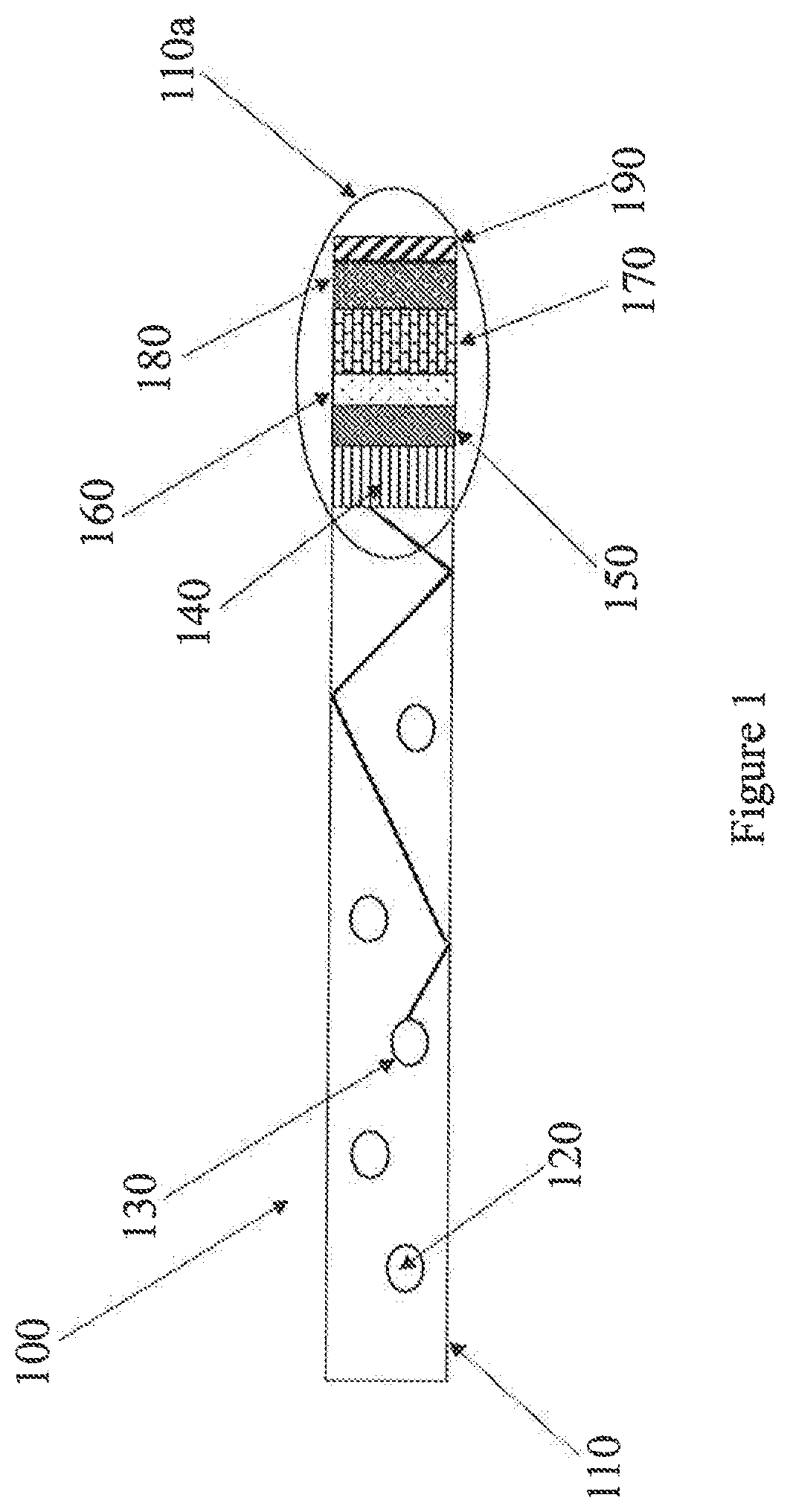
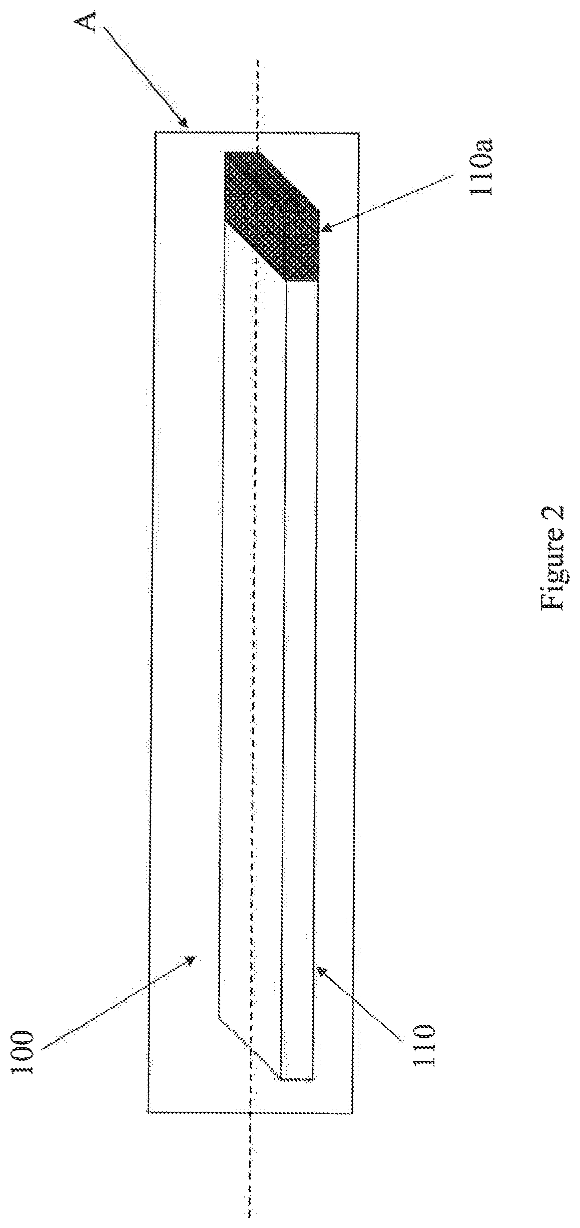
A photovoltaic device or solar device including at least one luminescent solar concentrator (LSC) having an upper surface, a lower surface and one or more external sides; at least one perovskite-based photovoltaic cell or solar cell positioned on the outside of at least one of the external sides of said luminescent solar concentrator (LSC), the perovskite being selected from organometal trihalides. The photovoltaic device or solar device may be used advantageously in various applications necessitating the production of electrical energy by utilising light energy, in particular solar radiation energy such as, for example: building integrated photovoltaic (BIPV) systems, photovoltaic windows, greenhouses, photobioreactors, noise barriers, lighting equipment, design, advertising, automotive industry. Moreover, the photovoltaic device or solar device can be used both in stand-alone mode and in modular systems.
Description
[0001]This application claims priority under 35 U.S.C. § 119(a) to Italian Patent Application No. 102018000008110 filed on Aug. 17, 2018 and is a national phase application under 35 U.S.C. § 371, of International Patent Application No. PCT / 162019 / 056892 filed on Aug. 14, 2019 the contents of which are incorporated by reference herein in their entirety.BACKGROUND OF THE DISCLOSURE1. Field of the Disclosure[0002]The present invention relates to photovoltaic devices (or solar devices) comprising luminescent solar concentrators (LSCs) and perovskite-based photovoltaic cells (or solar cells).[0003]More particularly, the present invention relates to a photovoltaic device (or solar device) comprising: at least one luminescent solar concentrator (LSC) having an upper surface, a lower surface and one or more external sides; at least one perovskite-based photovoltaic cell (or solar cell) positioned on the outside of at least one of the external sides of said luminescent solar concentrator (LS...
Claims
Application Information
Patent Timeline
Application Date:The date an application was filed.
Publication Date:The date a patent or application was officially published.
First Publication Date:The earliest publication date of a patent with the same application number.
Issue Date:Publication date of the patent grant document.
PCT Entry Date:The Entry date of PCT National Phase.
Estimated Expiry Date:The statutory expiry date of a patent right according to the Patent Law, and it is the longest term of protection that the patent right can achieve without the termination of the patent right due to other reasons(Term extension factor has been taken into account ).
Invalid Date:Actual expiry date is based on effective date or publication date of legal transaction data of invalid patent.
Patent Type & AuthorityApplications(United States)

