
Multipass laser amplifier and no-optical-power beam steering element

a laser amplifier and beam steering technology, applied in the field of laser amplification, can solve the problems of thermal lens aberration, limit the amplified power that can be extracted from the amplifier, and thermal lens aberration, etc., and achieve the effects of high power, high average power, and large siz

Pending Publication Date: 2022-04-28
COHERENT KAISERSLAUTERN
View PDF7 Cites 2 Cited by
  • Summary
  • Abstract
  • Description
  • Claims
  • Application Information

AI Technical Summary

Benefits of technology

The patent describes a new way to amplify light using a special laser crystal. To achieve the best results, the pump beam that powers the laser crystal should be strong and large in size. This is because a larger pump beam helps to protect the crystal from damage and also helps to achieve the best performance with maximum extraction of the available gain. By using a no-optical-power beam steering system, the seed beam is directed through the crystal several times, and this helps to keep the beam size large and prevents it from damaging the crystal. The result is a more powerful and efficient laser amplifier that can be realized with simple optical layouts and fewer optical elements.

Problems solved by technology

At high pump intensities within the gain material, the temperature dependence of the thermal conductivity and temperature dependence of the thermo-optic coefficient cause aberrations in the thermal lens.
These aberrations will ultimately limit the amplified power that can be extracted from the amplifier.
Self-absorption of the amplified seed beam may further contribute to aberrations in the thermal lens.

Method used


Image

  • Multipass laser amplifier and no-optical-power beam steering element
  • Multipass laser amplifier and no-optical-power beam steering element
  • Multipass laser amplifier and no-optical-power beam steering element

Examples


Embodiment Construction

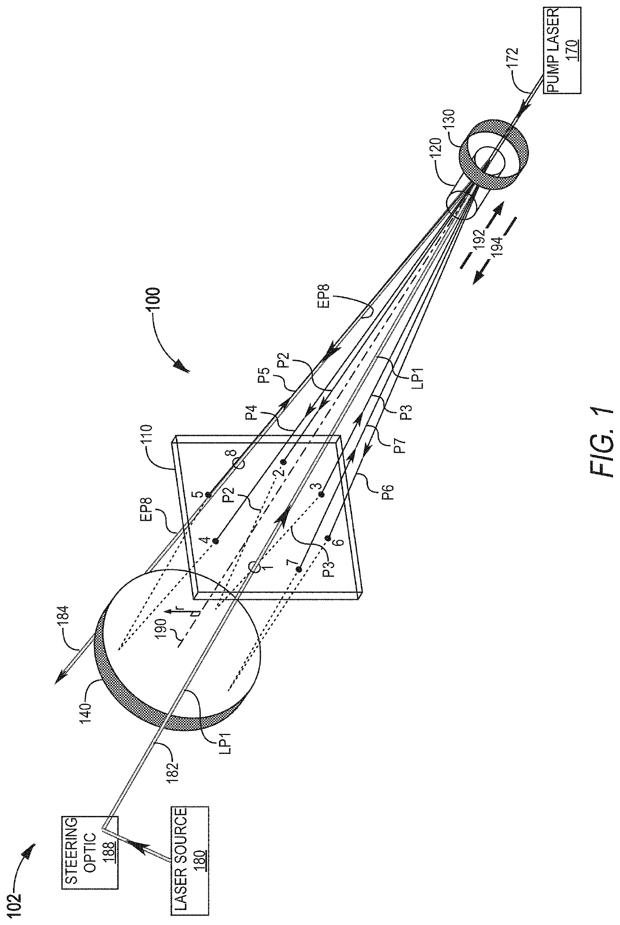
[0032]Referring now to the drawings, wherein like components are designated by like numerals, FIG. 1 illustrates one multipass laser amplifier 100 that utilizes a no-optical-power refractive beam steering element (BSE) 110 to direct a seed laser beam 182 through a laser-pumped gain crystal several times. Amplifier 100 includes BSE 110, a gain crystal 120, a mirror 130, and a mirror device 140. Amplifier 100 has a longitudinal axis 190 between mirror 130 and mirror device 140. BSE 110 and gain crystal 120 are positioned on longitudinal axis 190. Although depicted in FIG. 1 as being straight, longitudinal axis 190 may be folded, for example with one or more folding mirrors. BSE 110 steers seed beam 182 to make multiple passes between mirror 130 and mirror device 140 and thereby through gain crystal 120. The steering performed by BSE 110 is deflective and ensures that each pass of seed beam 182 through gain crystal 120 is on or near longitudinal axis 190 so as to overlap with a pump la...


PUM


Abstract

A multipass laser amplifier includes a mirror, a mirror device, a gain crystal, and refractive or diffractive beam-steering element. The gain crystal is positioned on a longitudinal axis of the multipass laser amplifier between the mirror and the mirror device. The beam-steering element is positioned on the longitudinal axis between the gain crystal and the mirror device. The beam-steering element has no optical power and deflects a laser beam, by refraction or diffraction, for each of multiple passes of the laser beam between the first mirror and the mirror device, such that each pass goes through the gain crystal for amplification of the laser beam and goes through a different respective off-axis portion of the beam-steering element. The no optical power of the beam-steering element enables maintaining a large beam size in the gain crystal, thereby facilitating amplification to high average power.

Description

TECHNICAL FIELD OF THE INVENTION[0001]The present invention relates in general to laser amplification, in particular to techniques for amplifying laser beams to a high average power.DISCUSSION OF BACKGROUND ART[0002]A typical arrangement for a high-power laser is a laser resonator, that generates a beam of laser radiation, and one or more laser amplifiers that amplify the power of this beam. Most laser amplifiers use either a bulk crystal or an optical fiber as the gain medium. Fiber amplifiers offer some convenience and are often advantageous but, for generation of laser radiation with a high peak power, the small cross section of the optical fiber leads to undesirable optical nonlinear effects, such as Raman processes transferring energy to other laser wavelengths and stimulated Brillouin scattering causing back-reflection of a portion of the laser radiation. Therefore, when the objective is to generate laser radiation with a high peak power, the preferred gain medium is generally...

Claims


Application Information

Patent Timeline
IPC IPC(8): H01S3/23H01S3/08H01S3/081H01S3/06
CPCH01S3/235H01S3/08095H01S3/0606H01S3/08054H01S3/08059H01S3/081H01S3/005H01S3/0071H01S3/094038H01S3/2325H01S3/1673H01S3/1611H01S3/08072H01S2301/03G02B5/04G02B27/4233
Inventor SCHÄFER, CHRISTOPH O.MCDONAGH, LOUISKNAPPE, RALF
Owner COHERENT KAISERSLAUTERN
Learn More