Film type liquid heater and uniform heating method thereof

Pending Publication Date: 2022-05-05
ZHEJIANG CHEER TECH CO LTD
View PDF6 Cites 1 Cited by
  • Summary
  • Abstract
  • Description
  • Claims
  • Application Information

AI Technical Summary

Benefits of technology

[0025]The present invention has the following beneficial effects. Since the liquid flows in the heating pipe, by using the heating film as a heating element, the time of heating liquid flow is long, the heating efficiency is high, and the degree of heating uniformity is high. The heating film is coated around the outer surface of the heating pipe, so the electrodes are prevented from being arranged in the liquid flow. Due to the presence of the flow splitting column, the liquid flow flows annularly in the heating pipe, and both the inner and outer sides of the annular liquid flow come into contact with the heat transfer wall,

Problems solved by technology

However, since the existing heaters have no specific design for the heating uniformity, there will be temperature difference for the immersion liquid flow in different positions after it flows through the existing heaters, due to the contact time difference of the interior immersion liquid with the heating element and the too short heat conduction time.
The immersion liquid with the temperature difference will affect the precision of subsequent temperature measurement and feedback adjustment and thus affect the exposure quality of the lithography system.
It is easily occurred that the resistance heating film generates heat unevenly, resulting in local temperature that is too high and reducing the service life or even leading to damage.
The

Method used


Image

  • Film type liquid heater and uniform heating method thereof
  • Film type liquid heater and uniform heating method thereof

Examples


embodiment 1

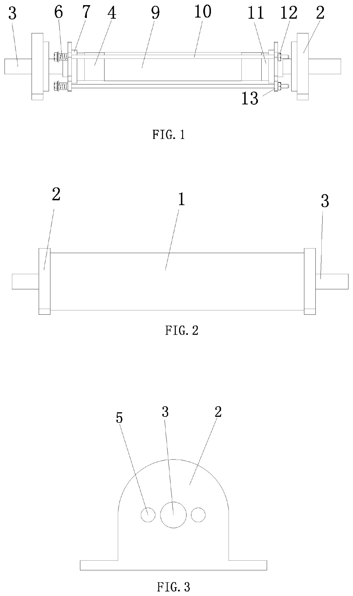
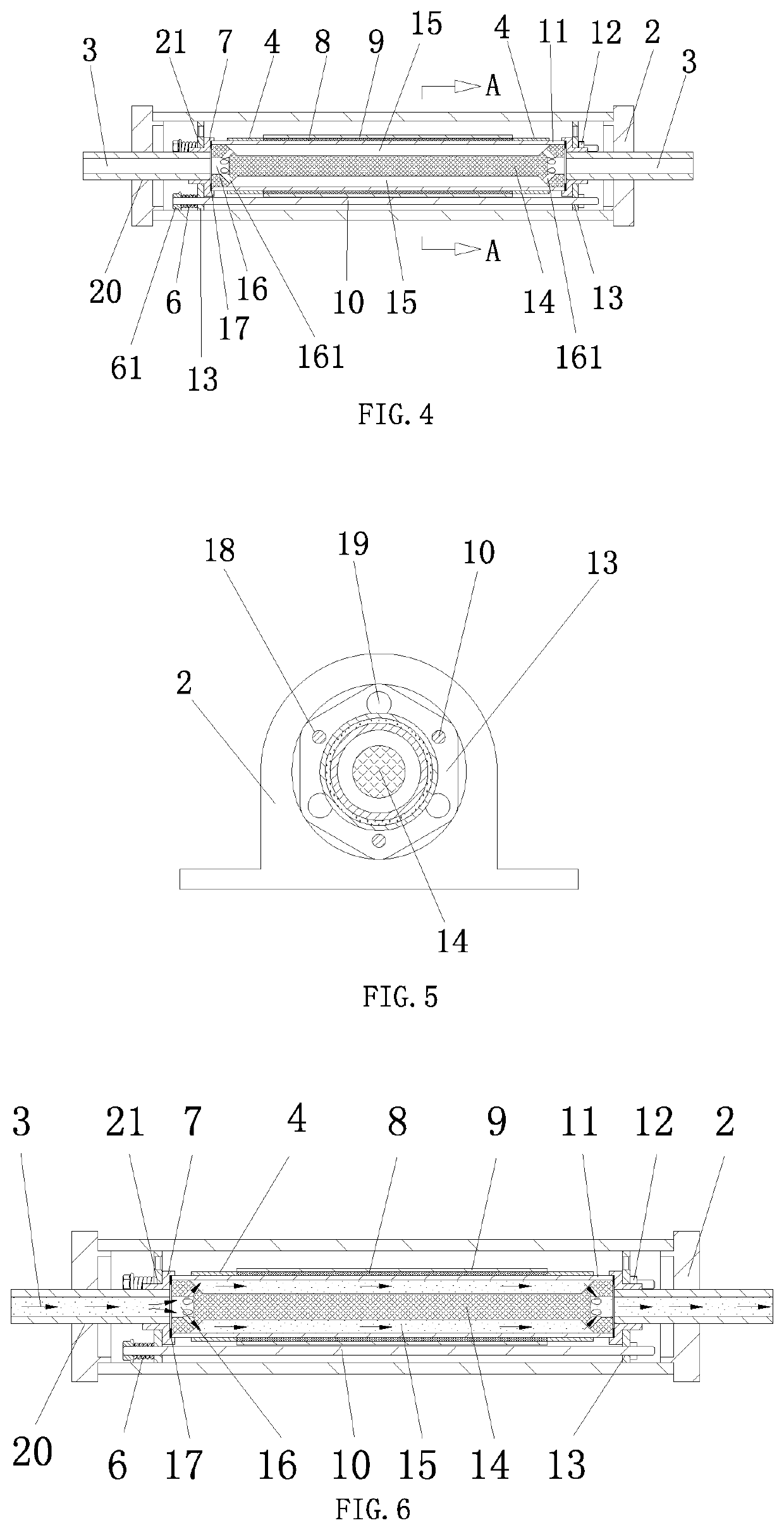
[0033]In the embodiment shown in FIGS. 1, 2, 3, 4, 5 and 6, a film type liquid heater is provided, including a heating pipe 11, a barrel 1, end fixation plates 2 and connecting pipes 3. The end fixation plates 2 are mounted and fixedly connected at two ends of the barrel 1. The heating pipe 11 is arranged in the barrel 1. Pipe ports 20 and first cable ports 5 run through the end fixation plates 2 at two ends, respectively. The connecting pipes 3 are fixedly mounted and connected in the pipe ports 20. Sealing connection components of the heating pipe 11 are mounted and connected at inner ends of the two connecting pipes 3. A heating film layer 8 is coated around the outer surface of the heating pipe 11. Electrode layers 4 are arranged at two axial ends of the heating film layer 8, respectively. The electrode layers 4 are connected to an external power supply through connecting wires. An insulating layer 9 is coated outside the heating film layer 8. A flow splitting column 14 is mount...

embodiment 2

[0035]In the embodiment shown in FIGS. 1, 2, 3, 4, 5 and 6, a uniform heating method for a film type liquid heater is provided, including the following steps.

[0036]A1. A wire connected to the electrode layers 4 described in Embodiment 1 is electrified by an external power supply, and energy is provided to heat the heating film layer 8 after the electrode layers 4 are electrified.

[0037]A2. The heating film layer 8 is electrified to generate heat, and the heat is conducted inward to the heating pipe 11 and the flow splitting column 14 described in Embodiment 1 and conducted outward to the barrel 1.

[0038]A3. Liquid flows into the film type liquid heater described in Embodiment 1 from an outer side of the connecting pipes 3 and then into the heating chamber 15 described in Embodiment 1 through the connecting pipes 3 and the flow splitting grooves 16 (as indicated by the arrow in FIG. 6).

[0039]A4. Since the heating chamber 15 is formed by the inner side of the heating pipe 11 and the flo...


PUM


Abstract

The present invention discloses a film type liquid heater and a uniform heating method thereof. End fixation plates are arranged at two ends of a barrel. A heating pipe is arranged in the barrel. Pipe ports run through the two end fixation plates, respectively. Connecting pipes are arranged in the pipe ports. Sealing connection components are arranged at inner ends of the two connecting pipes. A heating film layer is coated outside the heating pipe. Electrode layers are connected left and right sides of the heating film layer, and the electrode layers are connected to an external power supply. An insulating layer is coated outside the heating film layer. A flow splitting column is fixedly connected in the heating pipe. A heating chamber is formed between an inner side of the heating pipe and the flow splitting column. Flow splitting grooves are formed at left and right ends and on the inner side of the flow splitting column. Two outer ends of the flow splitting grooves are communicated with the connecting pipes, and the flow splitting grooves are communicated with the heating chamber. The heating film layer is electrified to generate heat. The heat is conducted inward to the heating pipe and the flow splitting column, and conducted outward to the barrel. Liquid flows into the heating chamber through the connecting pipes and the flow splitting grooves, so that the heating uniformity of the liquid flow flowing through the heating chamber is improved.

Description

TECHNICAL FIELD OF THE INVENTION[0001]The present invention relates to a liquid heater with high cleanliness and under precise temperature control, and in particular to a heating film type liquid heater and a uniform heating method thereof.BACKGROUND OF THE INVENTION[0002]Liquid with high cleanliness and precise temperature control is needed in many semiconductor industry applications. It is often necessary to provide pipeline heaters in the liquid pipeline system to precisely heat a liquid flow and control its temperature. Particularly, pipeline heaters suitable high-cleanliness applications are needed to adjust the temperature of liquid. For example, in an immersion lithography system, to realize better lithography effects and higher exposure quality, it is necessary to fill immersion liquid flowing stably between a projection lens and a wafer substrate. To ensure that the immersion liquid flow influences minimally on the laser beam that passes through the immersion liquid flow, i...

Claims


Application Information

Patent Timeline
IPC IPC(8): F24H1/12F24H1/00F24H1/10H05B3/42
CPCF24H1/121F24H1/0018H05B2203/021H05B3/42F24H2250/02F24H1/106F24H9/1818F24H9/2028H05B3/46H05B3/145H05B2203/011H05B2203/013H05B2203/017H05B3/06
Inventor FU, XINLUO, ZHENGZHAO, YIWENDU, SENXU, NING
Owner ZHEJIANG CHEER TECH CO LTD
Why Eureka
Try Eureka