Sample identification

a sample and identification technology, applied in the field of sample identification, can solve the problems of limited field of view, shallow depth of field (dof), significant signal loss, etc., and achieve the effects of reducing cross-contamination, and reducing the number of samples

Pending Publication Date: 2022-05-19
K2R2 LLC
View PDF8 Cites 0 Cited by
  • Summary
  • Abstract
  • Description
  • Claims
  • Application Information

AI Technical Summary

Benefits of technology

[0007]In certain embodiments, it is desirable to provide a robust, compact Raman spectrometer that utilizes a single-use sample holder to eliminate cross-contamination and replaces the conventional optical elements with arrays of collection lenses, slits, and collimation lenses so as to achieve a larger FOV, greater DOF, and increased light capture and provide a spatially averaged determination of material characteristics across a sample without scanning the sample.

Problems solved by technology

Conventional Raman spectrometers suffer from a number of drawbacks including a limited Field of View (FOV), a high numerical aperture (NA) that inherently results in a shallow Depth of Field (DOF), and a significant loss of signal due to the use of a single narrow slit.
Maintaining the integrity of a sample of material when the sample is handled by multiple people and transferred between locations and organizations is a long-standing challenge.

Method used


Image

  • Sample identification
  • Sample identification
  • Sample identification

Examples


embodiments

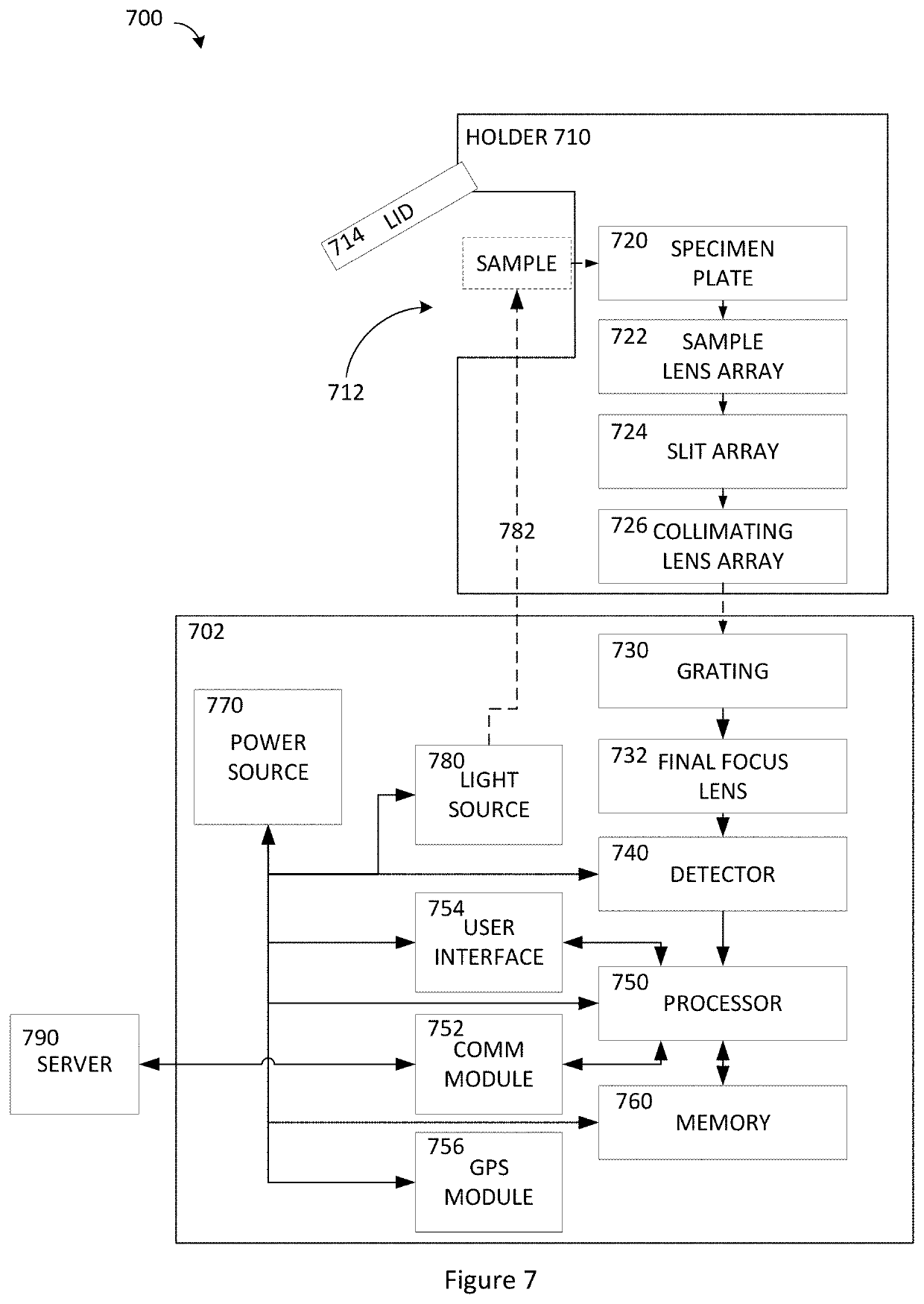
[0135]A1. An apparatus for analysis of a sample, comprising: a frame having a first axis; a sample holder coupled to the frame and disposed on the first axis; a transmissive diffraction grating coupled to the frame and disposed along the first axis such that light traveling along the first axis from the sample holder passes through the grating in a first direction; and a source coupled to the frame and configured to emit a first light to pass through the grating in a second direction that is opposite the first direction.

[0136]A2. The apparatus of A1, further comprising: a lens coupled to the frame; and a spatial filter coupled to the frame; wherein the lens and spatial filter are disposed along the first optical axis.

[0137]A3. The apparatus of A1, wherein a portion of the first light emitted by the source is diffracted by the grating to travel parallel to the first optical axis.

[0138]A4. The apparatus of A3, wherein: the light emitted by the source is monochromatic; the diffracted p...


PUM

PropertyMeasurementUnit
wavelengthaaaaaaaaaa
Ramanaaaaaaaaaa
first wavelengthaaaaaaaaaa

Abstract

A method of analyzing a sample is disclosed. The method includes the steps of measuring a spectral response of the sample, selecting a reference material having a Raman peak with a magnitude at a wave number, measuring a peak value in the spectral response at the wave number, and determining an amount of the reference material in the sample based in part on a ratio of the measured peak value to the magnitude of the Raman peak of the reference material.

Description

CROSS-REFERENCE TO RELATED APPLICATIONS[0001]This application claims priority to U.S. application 17 / 395,814 filed on Aug. 6, 2021 that claims priority to 63 / 105,763 filed Oct. 26, 2020, both of which are incorporated herein by reference in their entireties.STATEMENT REGARDING FEDERALLY SPONSORED RESEARCH OR DEVELOPMENT[0002]Not applicable.BACKGROUNDField[0003]The present invention generally relates to identification and handling of a sample of a material.Description of the Related Art[0004]Raman spectroscopy, named after Indian physicist C. V. Raman, is a spectroscopic technique used to identify materials. A source of monochromatic light illuminates a sample. The photons of the source light excite the molecules of the sample, which then emit photons that will be at a higher or lower energy level, compared to the incident photons, depending on the vibrational modes of the molecules of the sample. Every molecule has a characteristic “fingerprint” based on its structure. Comparison of...

Claims


Application Information

Patent Timeline
Patent Type & Authority Applications(United States)
IPC IPC(8): G01N21/65
CPCG01N21/65G01N2201/022G01N2021/651G01N2201/068
Inventor KAY, ROBERT LROSS, GRAHAM
Owner K2R2 LLC
Why Eureka
Try Eureka