Supercharge Your Innovation With Domain-Expert AI Agents!

Generation of positive and negative switch gate control voltages

Pending Publication Date: 2022-06-16
SKYWORKS SOLUTIONS INC
View PDF0 Cites 0 Cited by
  • Summary
  • Abstract
  • Description
  • Claims
  • Application Information

AI Technical Summary

Benefits of technology

The patent describes a method and system for controlling a high-power drive device using a positive and negative turn-on voltage based on a difference between a power supply voltage and a regulated power supply voltage. This allows for better control and regulation of the drive device. Additionally, the patent also describes a method of charging and discharging the control node of the drive device using a voltage regulator filter capacitor and power supplies. The technical effects of this invention include improved control and regulation of high-power drive devices, as well as improved efficiency in charging and discharging the control node.

Problems solved by technology

During normal operation, a large DC or transient voltage difference may exist between a domain of the processor system and a domain of the load system, thus requiring an isolation barrier between the processor system and the load system.
This alternative technique is more expensive than the solution described above because it requires more windings in a typical DC-DC converter power supply configuration.
The low-dropout regulator introduces additional overhead that increases the power dissipated by the gate driver and increases the amount of power to be delivered by the external power supplies.
Thus, the addition of LDO voltage regulators increases system power dissipation.
Moreover, the power that can be dissipated by the gate driver is limited by the package thermal characteristics.
Therefore, adding an on-chip LDO voltage regulator reduces the amount of overall gate charge that can be delivered to the power switch for a particular switching frequency.

Method used


Image

  • Generation of positive and negative switch gate control voltages
  • Generation of positive and negative switch gate control voltages
  • Generation of positive and negative switch gate control voltages

Examples


Embodiment Construction

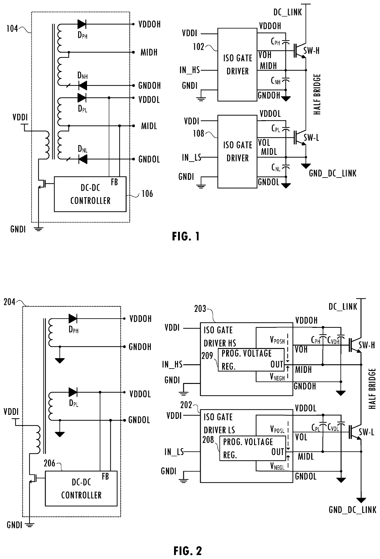
[0011]In at least one embodiment, a method for controlling a high-power drive device includes generating a positive turn-on voltage and a negative turn-off voltage for the high-power drive device by a first gate driver product based on a first power supply voltage received from a first integrated circuit terminal, a second power supply voltage received from a second integrated circuit terminal, and a regulated power supply voltage on a third integrated circuit terminal. The positive turn-on voltage is a difference between the first power supply voltage and the regulated power supply voltage and has a predetermined voltage level.

[0012]In at least one embodiment, a system for controlling a high-power drive device includes an output terminal of a driver integrated circuit, a first power supply terminal of the driver integrated circuit configured to receive a first power supply voltage, a second power supply terminal of the driver integrated circuit configured to receive a second power ...


PUM


Abstract

A technique for powering gate drivers in a half-bridge configuration uses a single external power supply to power each gate driver. A single on-chip regulator regulates the positive turn-on voltage for each switch. The regulator overhead, is also used as the negative voltage for turn-off, thus transferring the low-frequency variation of the external power supply to the negative turn-off voltage. Accordingly, a single on-chip regulator generates both the positive turn-on voltage and the negative turn-off voltage. In at least one embodiment, reuse of the switch turn-off current further reduces on-chip power dissipation. The on-chip regulator's output filter capacitor discharges during turn-on of the external power switching device. During turn-off, the current that discharges the switch gate capacitance recharges the regulator filter capacitor.

Description

CROSS-REFERENCE TO RELATED APPLICATION(S)[0001]This application claims the benefit of U.S. Provisional Application No. 63 / 125,226, entitled “ON-CHIP GENERATION OF POSITIVE AND NEGATIVE SWITCH GATE CONTROL VOLTAGES FOR GATE DRIVER APPLICATIONS,” naming Ion C. Tesu, Joselyn Torres-Torres, Stefan N. Mastovich, James E. Heckroth, Krishna Pentakota, and Long Nguyen as inventors, filed on Dec. 14, 2020, which application is incorporated herein by reference.BACKGROUNDField of the Invention[0002]This disclosure is related to integrated circuits, and more particularly to voltage regulation circuits.Description of the Related Art[0003]In a typical control application, a processor system provides one or more control signals for controlling a load system. During normal operation, a large DC or transient voltage difference may exist between a domain of the processor system and a domain of the load system, thus requiring an isolation barrier between the processor system and the load system. For e...

Claims


Application Information

Patent Timeline
IPC IPC(8): H03K17/567H02M1/08
CPCH03K17/567H02P27/06H03K2217/0081H02M1/08H02M1/0006H02M7/5387H03K17/14
Inventor TESU, ION CONSTANTINTORRES-TORRES, JOSELYNMASTOVICH, STEFAN NOELHECKROTH, JAMES EDWARDPENTAKOTA, KRISHNANGUYEN, LONG VAN
Owner SKYWORKS SOLUTIONS INC
Features
  • R&D
  • Intellectual Property
  • Life Sciences
  • Materials
  • Tech Scout
  • Unparalleled Data Quality
  • Higher Quality Content
  • 60% Fewer Hallucinations
Learn More