Power management system, server, and power supply and demand adjustment method

a technology of power management system and server, applied in the direction of electrochemical generators, battery/fuel cell control arrangement, transportation and packaging, etc., can solve the problems of progressing fuel cell degradation, achieve reduced number of times of decrease control, suppress fuel cell degradation, and reduce the effect of fuel cell degradation

Pending Publication Date: 2022-06-23
TOYOTA JIDOSHA KK
View PDF2 Cites 0 Cited by
  • Summary
  • Abstract
  • Description
  • Claims
  • Application Information

AI Technical Summary

Benefits of technology

[0011]In the configuration in (1) to (3) described above, the execution timings of the decrease control in the fuel cell electric vehicles are determined by the server. The server adjusts the execution timings of the decrease control in consideration of a state of all of the fuel cell electric vehicles, the request to adjust power supply and demand in the power grid, and the like. For example, the number of fuel cell electric vehicles that execute the decrease control within the prescribed time period (as an example, simultaneously) is restricted to or below the permissible number set in accordance with the request to adjust power supply and demand. Therefore, even when the electric power supplied from the fuel cell electric vehicles to the power gird decreases temporarily due to the decrease control, it is possible to remove the oxide films while suppressing an influence on the power grid. Thus, according to the configuration in (1) to (3) described above, the oxide films can be appropriately removed during power supply from the fuel cell electric vehicles to the power grid.
[0014]In the configuration in (4) and (5) described above, the server causes the fuel cell electric vehicles to simply execute the decrease control intermittently (preferably, regularly), regardless of the state of the fuel cell electric vehicles. Thus, a process executed by the server to manage the execution timings of the decrease control can be simplified.
[0016]In the configuration in (6) described above, in response to the request for the decrease control from each fuel cell electric vehicle, the server causes the fuel cell electric vehicle to execute the decrease control. When the decrease control is executed excessively, degradation of the fuel cell may progress. According to the configuration in (6) described above, the number of times of the decrease control is reduced, as compared with the case of executing the decrease control intermittently (regularly) as in (4) and (5) described above, and thus, degradation of the fuel cell can be suppressed.

Problems solved by technology

When the decrease control is executed excessively, degradation of the fuel cell may progress.

Method used


Image

  • Power management system, server, and power supply and demand adjustment method
  • Power management system, server, and power supply and demand adjustment method
  • Power management system, server, and power supply and demand adjustment method

Examples


first embodiment

[0033]

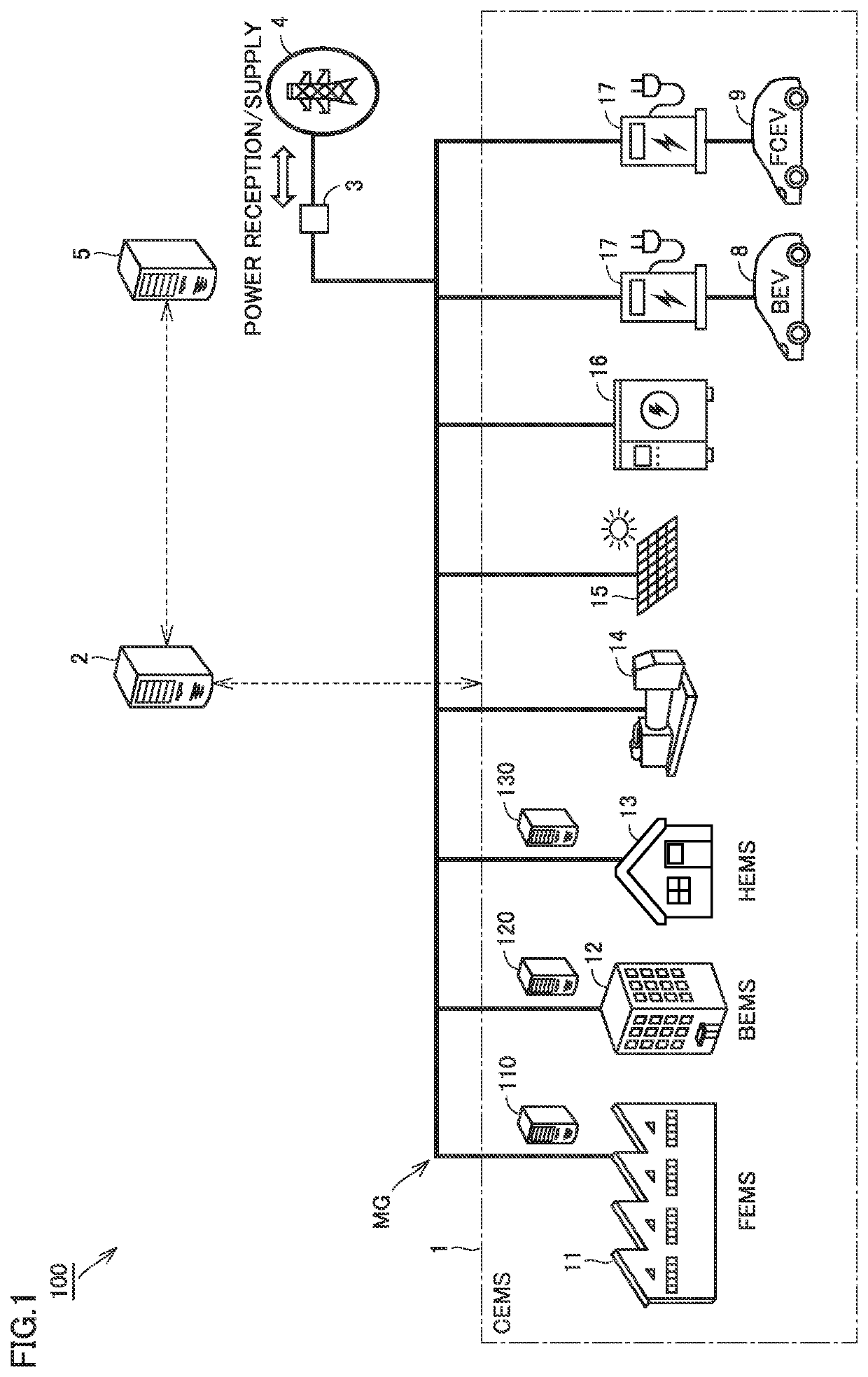
[0034]FIG. 1 shows a schematic configuration of a power management system according to a first embodiment of the present disclosure. A power management system 100 includes a CEMS 1, a CEMS server 2, a power reception and transformation facility 3, a power system 4, and a power transmission and distribution business operator server 5. CEMS stands for Community Energy Management System or City Energy Management System.

[0035]CEMS 1 includes a factory energy management system (FEMS) 11, a building energy management system (BEMS) 12, a home energy management system (HEMS) 13, a power generator 14, a variable renewable energy (VRE) source 15, an energy storage system (ESS) 16, a plurality of electric vehicle supply equipment (EVSEs) 17, a plurality of battery electric vehicles (BEVs) 8, and a plurality of fuel cell electric vehicles (FCEVs) 9. In CEMS 1, these components form a microgrid MG. Microgrid MG corresponds to an example of “power grid” according to the present disclosure.

[...

second embodiment

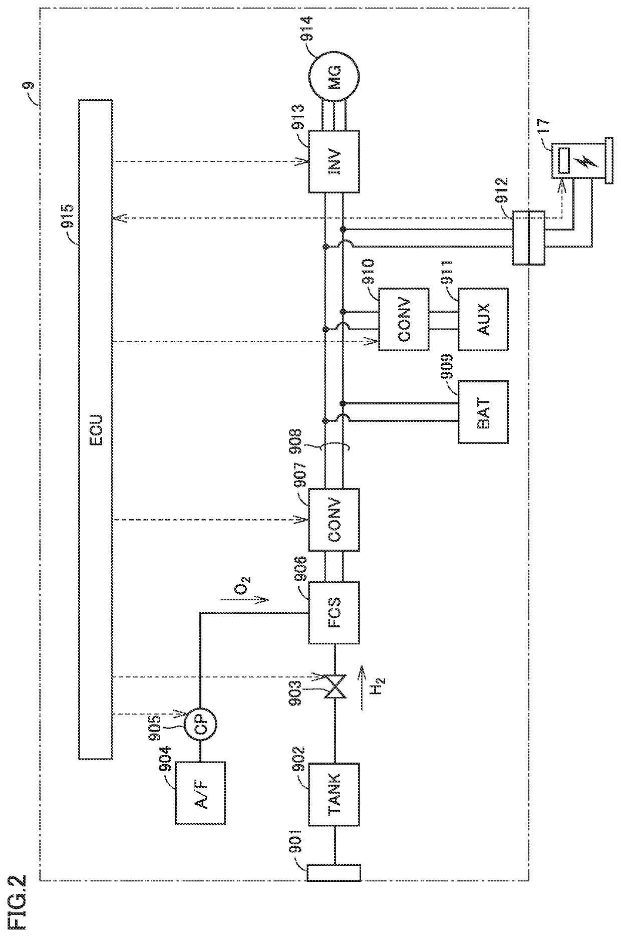
[0121]In the first embodiment, the configuration in which CEMS server 2 causes the plurality of FCEVs 9 to execute the decrease control regularly has been described. In a second embodiment, a configuration in which CEMS server 2 permits execution of the decrease control in accordance with a request from the FCEV 9 side will be described. Since an overall configuration of a power management system and a configuration of each FCEV 9 in the second embodiment are equivalent to the configurations described with reference to FIGS. 1 and 2, description will not be repeated.

[0122]FIG. 8 is a flowchart showing a power supply and demand adjustment method in the second embodiment. The processing in S31 to S33 is similar to the processing in S1 to S13 in the first embodiment (see FIG. 7). When FCEVs 9 receive the external power feeding command from CEMS server 2 (YES in S41), FCEVs 9 perform external power feeding with P1 in a normal state (S42).

[0123]Generally, when an oxide film is formed on ...


PUM

PropertyMeasurementUnit
voltageaaaaaaaaaa
voltageaaaaaaaaaa
electric poweraaaaaaaaaa

Abstract

A power management system includes power adjustment resources (including FCEVs) electrically connected to a microgrid, and a CEMS server that manages the power adjustment resources. Each of FCEVs includes: a supply valve that adjusts an amount of hydrogen supplied to an FC stack; a compressor that adjusts an amount of oxygen supplied to the FC stack; and an ECU. The ECU executes decrease control that temporarily decreases at least one of the amount of hydrogen supplied to the FC stack and the amount of oxygen supplied to the FC stack. The CEMS server determines execution timings of the decrease control in FCEVs during power supply to the microgrid.

Description

[0001]This nonprovisional application is based on Japanese Patent Application No. 2020-212342 filed on Dec. 22, 2020 with the Japan Patent Office, the entire contents of which are hereby incorporated by reference.BACKGROUNDField[0002]The present disclosure relates to a power management system, a server, and a power supply and demand adjustment method.Description of the Background Art[0003]Japanese Patent Laying-Open No. 2019-129062 discloses a controller for a fuel cell that suppresses degradation of the fuel cell.SUMMARY[0004]It is known that an oxide film may be formed on a catalyst electrode of a fuel cell. When the oxide film is formed, the power generation efficiency of the fuel cell decreases. In order to maintain the power generation efficiency of the fuel cell, it is required to remove, as appropriate, the oxide film formed on the catalyst electrode.[0005]In recent years, attention has been focused on a microgrid in which a plurality of power adjustment resources (e.g., a di...

Claims


Application Information

Patent Timeline
Patent Type & Authority Applications(United States)
IPC IPC(8): H01M8/04828H01M8/04119B60L58/30B60L58/40
CPCH01M8/0494H01M8/04119H01M2250/20B60L58/40B60L58/30H02J3/00H02J3/38H02J3/381H02J3/46H02J3/466B60L55/00H01M8/04089H01M8/043H01M8/04753H02J2300/30Y02E60/00
Inventor HAMADA, SHIGETAKAHIROSE, HARUKAHORII, YUSUKENAKAMURA, TORUSANO, TAKAAKI
Owner TOYOTA JIDOSHA KK
Why Eureka
Try Eureka