
Turbomachine blade with improved cooling

Pending Publication Date: 2022-06-30
SAFRAN +1
View PDF6 Cites 0 Cited by
  • Summary
  • Abstract
  • Description
  • Claims
  • Application Information

AI Technical Summary

Benefits of technology

The invention relates to a turbine blade for a turbomachine such as a turbojet. The blade has a root for mounting it in a cell of the disc, and a hollow vane extending from the root in a radial spanwise direction ending in a tip forming a squealer. The blade has a middle circuit of the trombone type with ducts that are mainly radial, and a cavity under the squealer that is fed by a central duct located between the upper surface wall and the middle duct. The blade also has a cooling system to prevent overheating of the lower surface wall close to the tip. The technical effects of the invention include improved cooling of the blade, reduced airflow resistance, and improved cooling of the cavity under the squealer.

Problems solved by technology

Nevertheless, it appears that the cooling of high pressure turbine blades requires a constant improvement effort, in particular due to the continual evolution of operating conditions, manufacturing methods and performance requirements.

Method used


Image

  • Turbomachine blade with improved cooling
  • Turbomachine blade with improved cooling
  • Turbomachine blade with improved cooling

Examples


Embodiment Construction

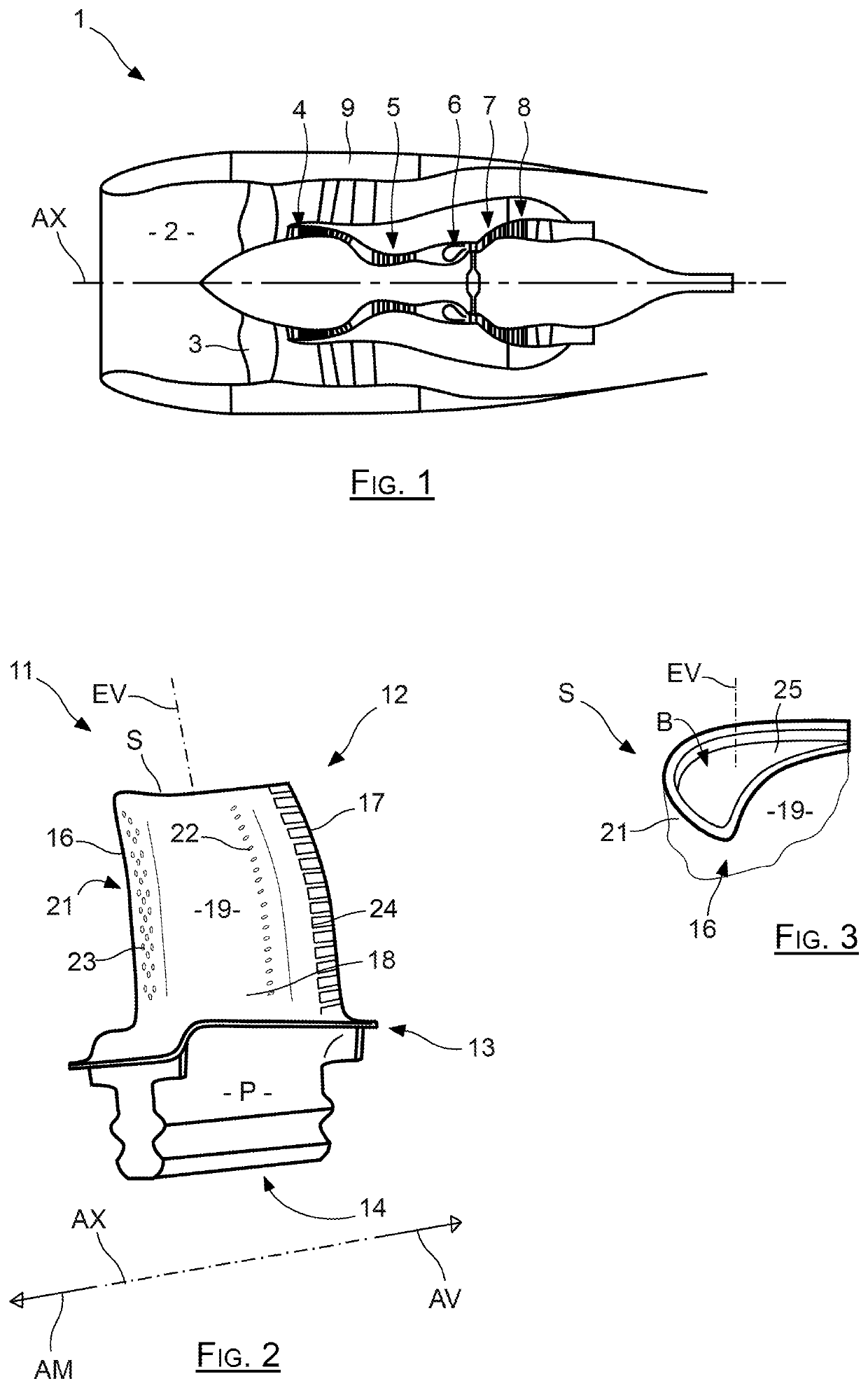
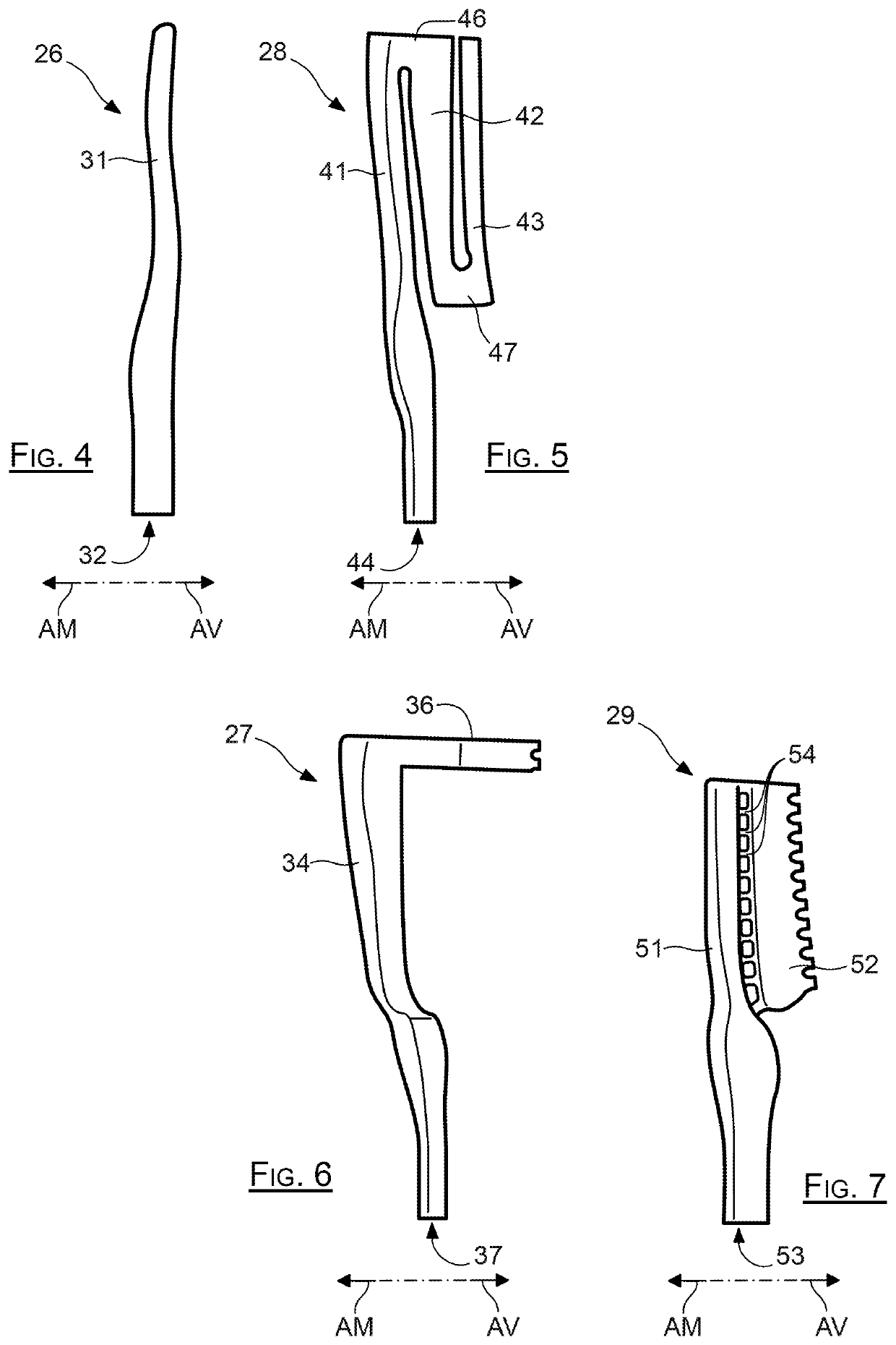
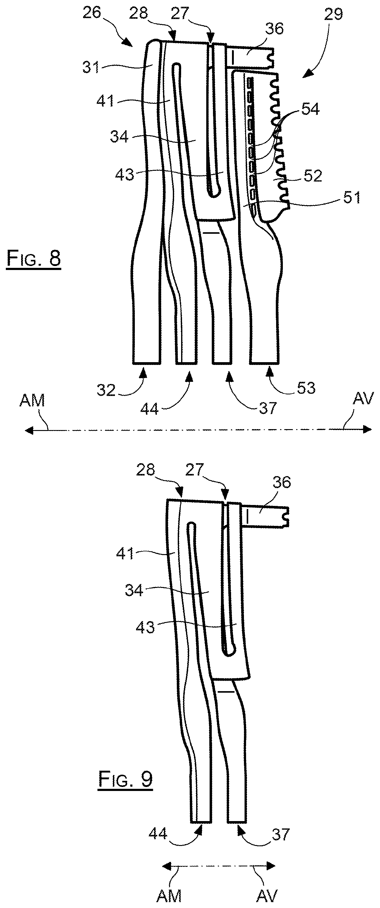
[0009]To this end, the object of invention is a turbine blade of a turbomachine such as a turbojet, intended to be mounted around an axis of rotation on a rotor disc rotating around an axis of rotation, comprising a root for mounting it in a cell of the disc, and a hollow vane extending from the root in a radial spanwise direction ending in a tip forming a squealer, the vane comprising a lower surface wall and an upper surface wall, as well as a leading edge, a trailing edge and a tip wall delimiting a bottom of the squealer, and by which the lower surface wall is connected to the upper surface wall, this vane also comprising:[0010]a middle circuit of the trombone type, including a first duct collecting air at the root and which is connected by a first elbow to a second duct which is connected by a second elbow to a third duct, these first second and third ducts being mainly radial, the second and third radial ducts being located between the first duct and the trailing edge;[0011]a ...


PUM


Abstract

A turbine vane includes a root carrying a blade terminated by a squealer tip, the blade having intrados and extrados walls, a leading edge, a trailing edge, and a tip wall delimiting a bottom of the squealer tip, by which the intrados wall is connected to the extrados wall. The blade also includes: a serpentine median circuit, including a first radial pipe that collects air at the root and is connected by a first bend to a second radial pipe that is connected by a second bend to a third radial pipe; a cavity under the squealer tip running along the extrados wall and extending from a central region of the squealer tip to the trailing edge; and a central radial pipe collecting air at the root and extending between at least two of the three pipes of the median circuit and directly supplying the cavity under the squealer tip.

Description

TECHNICAL FIELD[0001]The invention relates to a blade for an aircraft engine of the turbomachine type, such as for example a turbojet or a turboprop, and it applies in particular to a high pressure type turbine blade.PRIOR ART[0002]In such a turbojet-type engine, marked with 1 in FIG. 1, the air is taken into an inlet sleeve 2 to pass through a fan including a series of rotating vanes 3 before splitting into a central primary flow and a secondary flow surrounding the primary flow.[0003]The primary flow is compressed by low pressure 4 and high pressure 5 compressors before reaching a combustion chamber 6, after which it expands through a high pressure turbine 7 and a low pressure turbine 8, before being discharged while generating an auxiliary thrust. The secondary flow is propelled directly by the fan to generate a main thrust.[0004]Each turbine 7, 8 includes series of blades which are radially oriented and regularly spaced around an axis of rotation AX, an outer casing 9 surroundin...

Claims


Application Information

Patent Timeline
IPC IPC(8): F01D5/18B22C9/10
CPCF01D5/187F05D2260/20F05D2220/30B22C9/106F05D2230/211F05D2250/185B22C9/22Y02T50/60
Inventor OSTINO, LÉANDREAUZILLON, PIERRE GUILLAUMESLUSARZ, MICHELENEAU, PATRICEDE ROCQUIGNY, THOMAS OLIVIER MICHEL PIERRECARIOU, ROMAIN PIERRETANG, BA-PHUCROLLINGER, ADRIEN BERNARD VINCENTSIMON, VIANNEY
Owner SAFRAN
Learn More