
Optical Module

Pending Publication Date: 2022-07-14
HISENSE BROADBAND MULTIMEDIA TECH
View PDF0 Cites 0 Cited by
  • Summary
  • Abstract
  • Description
  • Claims
  • Application Information

AI Technical Summary

Benefits of technology

The present patent provides an optical module with improved heat dissipation capabilities. The module includes a circuit board, an optical chip, a lens assembly, and a heat dissipation structure. The heat dissipation structure includes a first heat dissipation member located below the lens assembly and outside of the lens assembly, a second heat dissipation member located outside of the lens assembly and opposite the first member, and a thermally conductive member disposed between the first and second members. The heat generated by the optical chip is conducted to the outside of the lens assembly through the first member, while the second member receives and diffuses the heat. The thermally conductive member is in thermal contact with the upper enclosure for conducting heat to the enclosure. The heat dissipation structure helps to prevent overheating of the optical chip and ensures optimal performance of the optical module.

Problems solved by technology

If the heat cannot be dissipated quickly, an environment temperature of the optical module may keep rising, which may deteriorate the performance of the optical module.

Method used


Image

  • Optical Module
  • Optical Module
  • Optical Module

Examples


embodiment 1

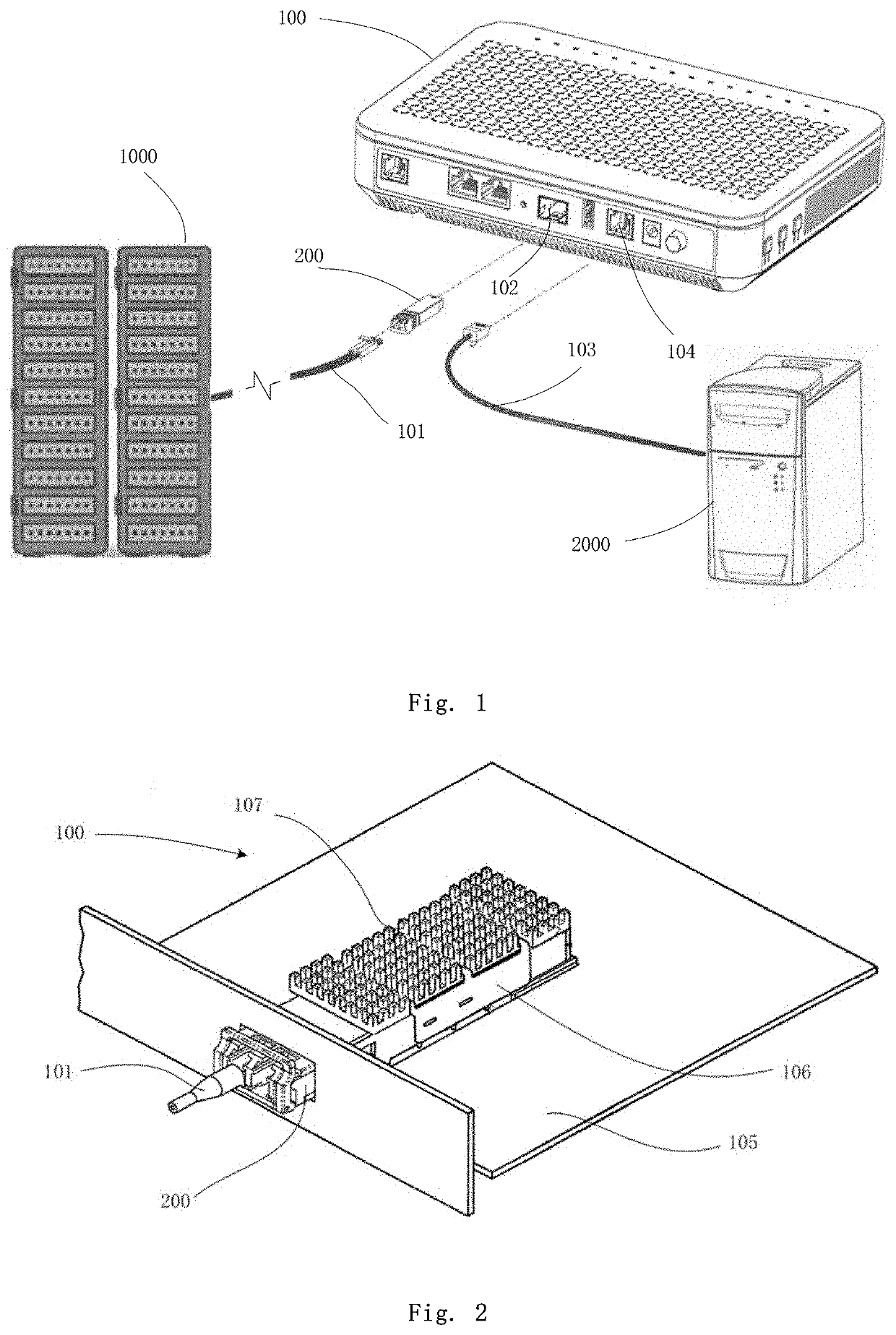
[0035]FIG. 1 shows a schematic diagram illustrating a connection relationship of an optical communication terminal. As shown in FIG. 1, the optical communication system includes a remote server 1000, a local information processing device 2000, an optical network terminal 100, an optical module 200, an optical fiber 101 and a network cable 103.

[0036]One end of the optical fiber 101 is connected to the remote server 1000, and the other end thereof is connected to the optical network terminal 100 through the optical module 200. The optical fiber itself may support long-distance signal transmission, such as several-kilometer (6-kilometer to 8-kilometer) signal transmission. On this basis, infinite-distance transmission may be achieved theoretically if a repeater is used. Therefore, in a typical optical communication system, a distance between the remote server 1000 and the optical network terminal 100 may typically reach several kilometers, tens of kilometers, or hundreds of kilometers....


PUM


Abstract

This application discloses an optical module. A circuit board is provided with a first heat dissipation member. One end of the first heat dissipation member is attached with an optical chip, with a lens assembly covering the optical chip. The other end extends outwardly from a coverage region of the lens assembly, so that heat generated by the optical chip is diffused to outside of the lens assembly. One end of the first heat dissipation member away from the lens assembly is provided with a second heat dissipation member whose upper surface being provided with a thermally conductive member. An upper surface of the thermally conductive member is thermally coupled with an upper enclosure. The second heat dissipation member conducts the heat diffused by the first heat dissipation member to the upper enclosure via the thermally conductive member. Thus, heat dissipation is achieved via the upper enclosure.

Description

[0001]This application claims the priority to the Application No. 202010018782.7, filed with the China National Intellectual Property Administration on Jan. 8, 2020, and the priority to the Application No. 202010018784.6, filed with the China National Intellectual Property Administration on Jan. 8, 2020, which are incorporated herein by references in their entirety.FIELD OF THE INVENTION[0002]This application relates to the field of optical communication technologies, and in particular, to an optical module.BACKGROUND OF THE INVENTION[0003]An optical module includes a printed circuit board (PCB for short), a laser disposed on the printed circuit board, a detector, driving chips for driving the laser and the detector, and other components. The components are soldered on corresponding pads of the printed circuit board. Each component may generate heat during operation. If the heat cannot be dissipated quickly, an environment temperature of the optical module may keep rising, which may...

Claims


Application Information

Patent Timeline
IPC IPC(8): G02B6/42
CPCG02B6/4268G02B6/428G02B6/4206G02B6/4246G02B6/4204G02B6/4269
Inventor YAO, JIANWEIDONG, BENZHENGXU, FABUYU, DONGMEILIU, FEILUO, CONGWENMU, JIANWEI
Owner HISENSE BROADBAND MULTIMEDIA TECH
Features
  • Generate Ideas
  • Intellectual Property
  • Life Sciences
  • Materials
  • Tech Scout
  • Unparalleled Data Quality
  • Higher Quality Content
  • 60% Fewer Hallucinations
Learn More