Low Thermal Capacity Micro-Bolometer and Associated Manufacturing Method

a micro-bolometer and low thermal capacity technology, applied in the field of electromagnetic radiation detection, can solve the problems of bolometric detector signal-to-noise ratio deficiency, limit constraining, image degradation,

Pending Publication Date: 2022-07-21
LYNRED
View PDF0 Cites 1 Cited by
  • Summary
  • Abstract
  • Description
  • Claims
  • Application Information

AI Technical Summary

Benefits of technology

[0029]In addition to the removal of the absorbing material at the level of the recesses, the dielectric layer is also removed at this level so that the mass of the membrane is decreased, thus improving its time constant.
[0054]The invention thus enables to limit the mass of the membrane without too significantly complicating the manufacturing process, since it is not necessary to implement an additional step.

Problems solved by technology

Indeed, the use of detectors having too low a time constant as compared with the rapidity of the events of the scene causes a degradation of the image, for example, the occurrence of phenomena of drag, fuzziness, or deformation of the observed object.
Further, there exist many cases for which the bolometric detectors have a signal-to-noise ratio deficiency, in particular all defense applications intended for the remote detection and identification of targets.
An obvious solution to decrease the constraint on the tradeoff between the signal-to-noise ratio and the time constant comprises decreasing the thermal capacity of the membrane, but it has constraining limits.
However, for mechanical hold reasons, the thickness of the membrane cannot be decreased below a limiting thickness, close to 0.1 micrometer.
Further, it can be envisaged to decrease the lateral dimensions of the membrane but this solution causes an absorption deficiency associated with a decrease in the collection surface area of the absorber.

Method used


Image

  • Low Thermal Capacity Micro-Bolometer and Associated Manufacturing Method
  • Low Thermal Capacity Micro-Bolometer and Associated Manufacturing Method
  • Low Thermal Capacity Micro-Bolometer and Associated Manufacturing Method

Examples


Embodiment Construction

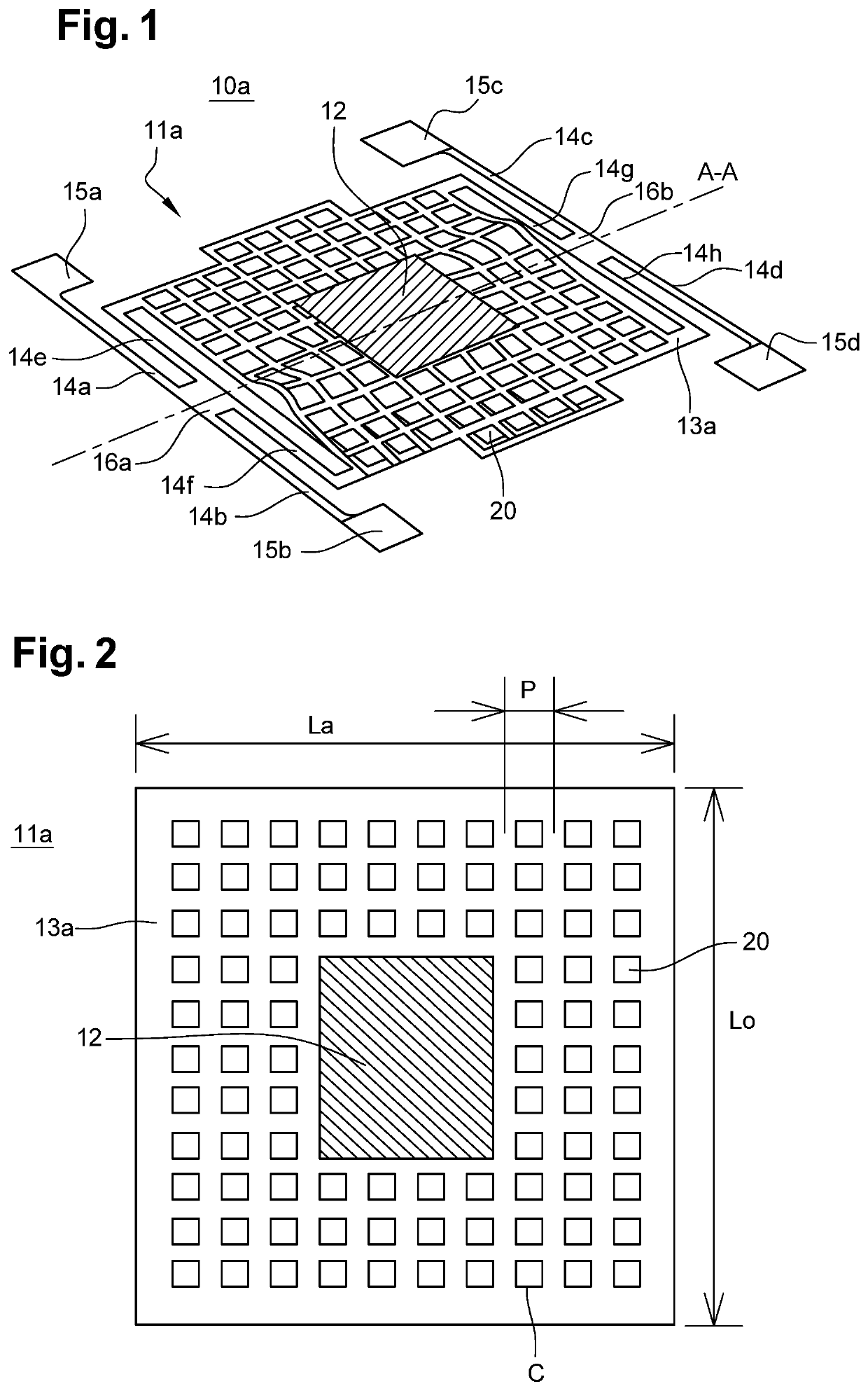
[0066]FIG. 1 illustrates an imaging micro-bolometer 10a according to the invention during a simulation of the deformations of its membrane 11a. This membrane 11a is assembled in suspension above a substrate 30. For this purpose, four anchor nails 15a-15d are attached to a substrate 30 and extend perpendicularly thereto. The example described in FIG. 1 is non-limiting and the invention may be implemented with only two anchor nails and two support arms. The structure of FIG. 1 is advantageous since the use of four anchor nails 15a-15d and of four support arms 14a-14h enables to thin membrane 11a by limiting its mechanical deformation, and thus as a corollary, to decrease its mass.

[0067]Each support arm 14a-14h is formed of two portions coupled by a bearing 16a-16b common to two support arms 14a-14h. More precisely, a first portion 14a of a first support arm is coupled on the anchor nail 15a located at the top left of membrane 11a, and this first portion 14a is connected to a bearing 1...


PUM

PropertyMeasurementUnit
total thicknessaaaaaaaaaa
time constantaaaaaaaaaa
thicknessaaaaaaaaaa

Abstract

An infrared imaging micro-bolometer integrates a membrane assembled in suspension on a substrate by support arms. The membrane includes an absorbing material configured to capture infrared radiations and a thermometric material connected to the absorbing material configured to perform a transduction of the infrared radiations captured by the absorbing material The thermometric material is arranged on a surface area smaller than 0.4 times a surface area of the membrane. The membrane also includes at least one central dielectric layer arranged between the absorbing material and the thermometric material. Recesses are formed in the absorbing material and in the at least one dielectric layer in portions of the membrane devoid of the thermometric material.

Description

TECHNICAL FIELD[0001]The present disclosure relates to the field of the detection of electromagnetic radiations and, more precisely, to the detection of infrared radiations. The invention concerns, on the one hand, the structure of a micro-bolometer having a membrane with a low thermal capacity, without for the absorption of the infrared flux to be impacted by this and, on the other hand, an associated forming method.BACKGROUND[0002]In the field of detectors implemented for infrared imaging, it is known to use devices arranged in an array, likely to operate at room temperature, that is, requiring no cooling to very low temperatures, conversely to detection devices called “quantum detectors” which require an operation at a very low temperature.[0003]These detectors conventionally use the variation of a physical quantity of an appropriate material or assembly of materials, according to temperature, around 300 K. In the specific case of micro-bolometric detectors, which are the most cu...

Claims


Application Information

Patent Timeline
Patent Type & Authority Applications(United States)
IPC IPC(8): G01J5/02G01J5/22H04N5/33
CPCG01J5/024G01J2005/204H04N5/33G01J5/22G01J5/20G01J5/0853G01J2005/202
Inventor BOUDOU, NICOLASCORTIAL, SÉBASTIEN
Owner LYNRED
Why Eureka
Try Eureka