
Sensor assembly

Pending Publication Date: 2022-08-04
BREVILLE HLDG PTY LTD
View PDF0 Cites 0 Cited by
  • Summary
  • Abstract
  • Description
  • Claims
  • Application Information

AI Technical Summary

Benefits of technology

The patent describes a device with a nozzle that directs water pressure to the end of a sensor to clean it. This helps to keep the sensor clean and functioning properly.

Problems solved by technology

Repeated heating of water, particularly hard water, inside the appliance typically results in the formation of limescale.
Disadvantageously, limescale may be deposited on critical parts of sensors (such as negative temperature coefficient “NTC” type thermistors) employed in the appliance thereby impeding proper function and causing undermeasurement.

Method used


Image

  • Sensor assembly
  • Sensor assembly
  • Sensor assembly

Examples


Embodiment Construction

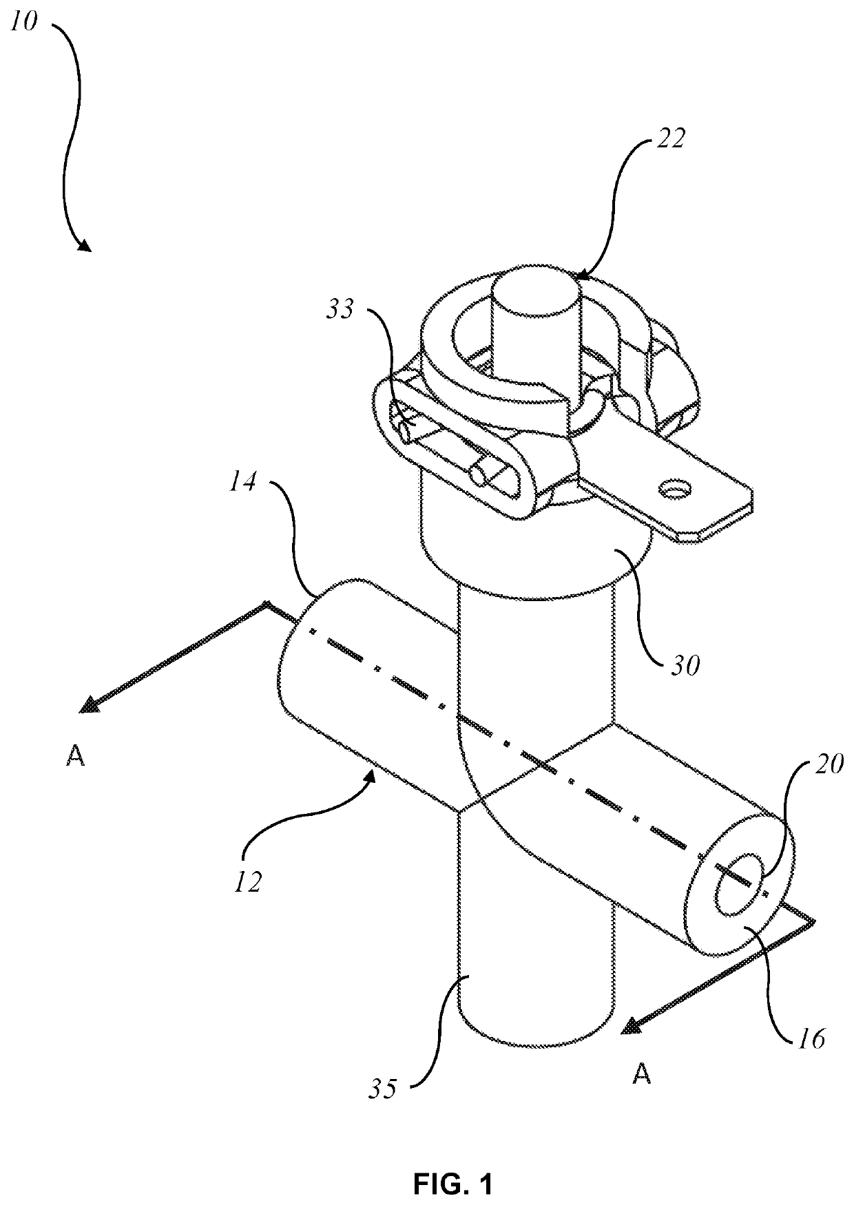
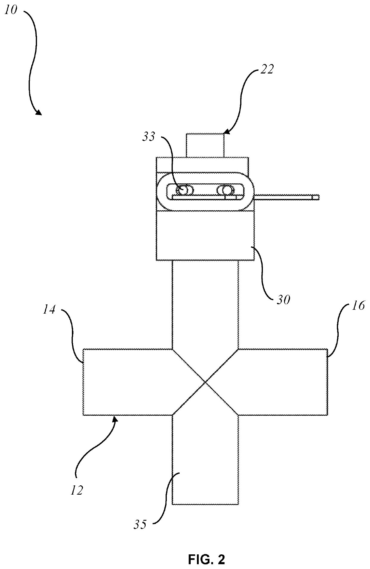
[0039]Referring firstly to FIGS. 1 to 3 of the drawings, there is schematically depicted a sensor assembly 10 for an appliance 100, 200. The appliance 100, 200 is configured to heat a liquid, such as water, for making a beverage, such as coffee.

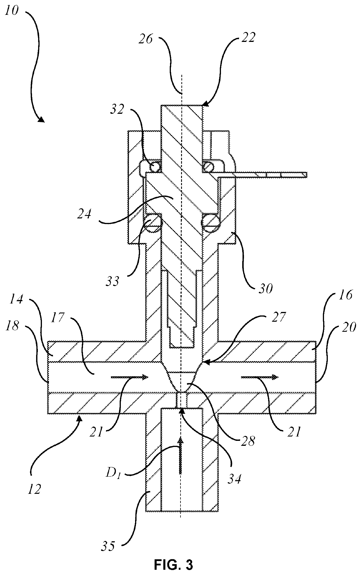
[0040]The assembly 10 includes a duct in the form of a tube 12 having longitudinally opposite first and second end portions 14, 16. As shown in FIG. 3, the tube 12 has an inlet 18 located adjacent the first end portion 14, and an outlet 20 located adjacent the second end portion 16. The tube 12 has a longitudinal sidewall 17 extending between the inlet 18 and the outlet 20 so as to provide a liquid flow path 21 extending linearly between the first and second end portions 14, 16.

[0041]The assembly 10 also includes a sensor 22 for measuring line parameters (such as temperature, pressure, flow, clarity and the like) of the liquid flowing along the path 21. In the preferred embodiment, the sensor 22 is an NTC type sensor configured to measure a t...


PUM


Abstract

An appliance (100, 200) for heating a liquid to make a beverage, the appliance (1) including: a sensor assembly (10) including: a duct (12) having an inlet (18) and an outlet (20), the duct (12) defining a liquid flow path (21) between the inlet (18) and the outlet (20) for the liquid; a sensor (22) having an operative end portion (28) in the flow path (21) for measuring line parameters of the liquid in the flow path (21); and a nozzle (34) to receive water under pressure and direct a water jet transverse to the flow path (21) and towards the operative end portion (28) of the sensor (22) to at least aid in cleaning the operative end portion (28) of the sensor (22).

Description

FIELD[0001]The present invention relates to sensor assemblies, and in particular but not exclusively, to sensor assemblies employed in appliances used to heat a liquid.BACKGROUND[0002]Known appliances used to heat a liquid such as kettles, coffee makers, tea makers etc., heat up water, for example, for use when making beverages. Repeated heating of water, particularly hard water, inside the appliance typically results in the formation of limescale. Disadvantageously, limescale may be deposited on critical parts of sensors (such as negative temperature coefficient “NTC” type thermistors) employed in the appliance thereby impeding proper function and causing undermeasurement. As more water is heated, more limescale is formed which may continue to be deposited on the sensors.OBJECT[0003]It is an object of the present invention to substantially overcome, or at least ameliorate, one or more of the above disadvantages.SUMMARY OF INVENTION[0004]In a first aspect, the invention provides an ...

Claims


Application Information

Patent Timeline
IPC IPC(8): A47J31/60A47J31/56A47J31/46B08B3/02
CPCA47J31/60A47J31/56A47J27/21066A47J31/468B08B3/02A47J31/461G01K13/026B05B1/3006G01K7/22A47J2202/00F24H15/219F24H15/288F24H15/14F24D2220/04
Inventor KONG, TAE-KYUNGLEUNG, ALEX MING DUKTOFAILI, ALIPSAROLOGOS, CONMCCLEAN, STEPHEN JOHN
Owner BREVILLE HLDG PTY LTD
Features
  • Generate Ideas
  • Intellectual Property
  • Life Sciences
  • Materials
  • Tech Scout
  • Unparalleled Data Quality
  • Higher Quality Content
  • 60% Fewer Hallucinations
Learn More