
Shielding device for use in medical imaging

a shielding device and medical imaging technology, applied in the field of medical imaging, can solve the problems of increased risk for the health of physicians, unpredictable nature of scattering radiation, and constant x-ray exposure during the procedur

Pending Publication Date: 2022-08-04
KONINKLJIJKE PHILIPS NV
View PDF0 Cites 1 Cited by
  • Summary
  • Abstract
  • Description
  • Claims
  • Application Information

AI Technical Summary

Benefits of technology

The present invention provides a user-friendly shielding device to lower the scatter radiation from a patient, reducing health hazards for physicians. The device allows the radiation to pass through a narrow cut-out in the blocking material, which can be rotated to expose any area between the center of the device and the edge. The primary X-ray beam can pass through the device, but the scatter radiation is substantially reduced. The shielding device can be mounted underneath an operating table to block the direct scatter radiation from the patient being treated.

Problems solved by technology

Still, the procedure exposes all medical staff in a hybrid operating room environment to a relatively large dose of radiation due to the need for live imaging, therefore resulting in constant x ray exposure during the procedure.
This excites the electron which can shift to another electron state, while the photon (now with slightly less energy) deflects in a random direction, hence causing the unpredictable nature of scatter radiation.
Therefore there is greater hazard for the physicians' health.
Movable ceiling mounted shields are however often misplaced or misused.
The shields can in some instances also hinder the movement of the physicians in the crowded hybrid operating room environment.
Wearable shielding, such as aprons, cause ergonomic discomfort because of the need to be made out of heavy elements (e.g. lead) with a certain thickness (hence, thick and rigid) and are without any pores and gaps (hence, breathable nor flexible).

Method used


Image

  • Shielding device for use in medical imaging
  • Shielding device for use in medical imaging
  • Shielding device for use in medical imaging

Examples


Embodiment Construction

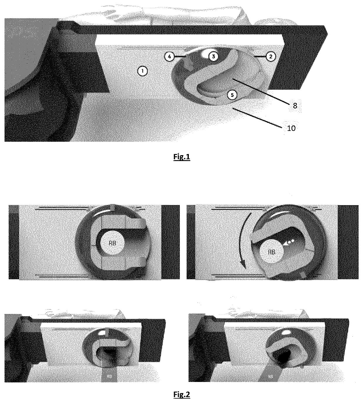
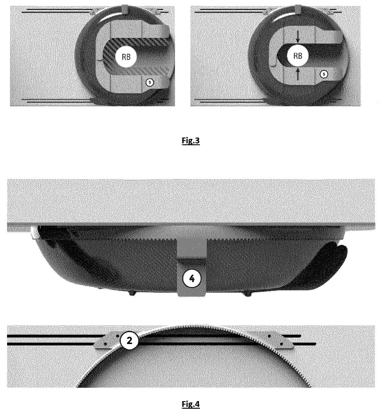
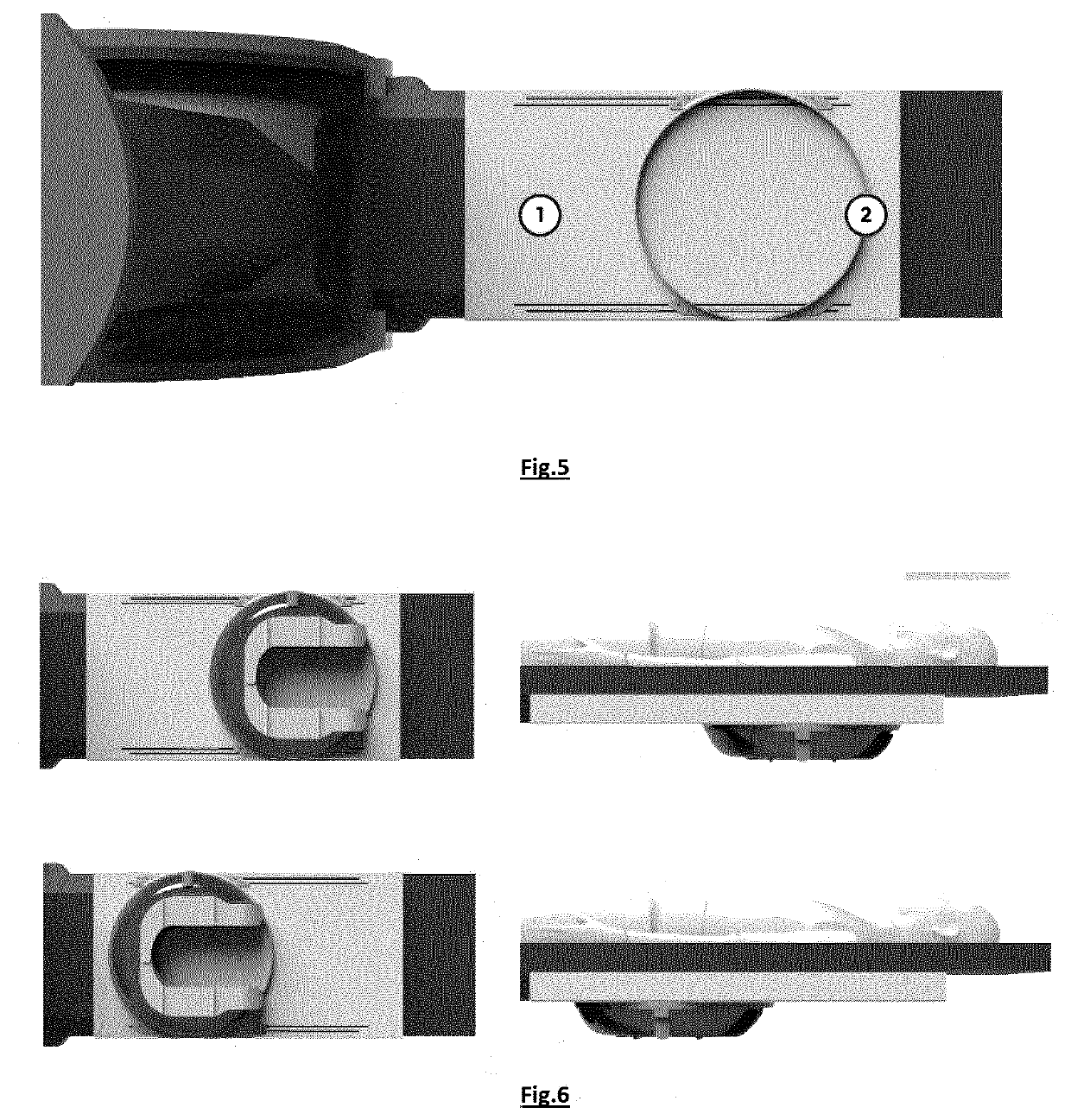
[0033]An embodiment of a shielding device as used with the present invention is illustrated in FIG. 1. The shielding device (10) has a rotatable structure with one or more plates in a radiation blocking material (6) wherein a narrow cut-out (8) is provided so that radiation transmission can pass. The structure can rotate around a rotation axis, which is in a preferred embodiment the central axis of the shielding device.

[0034]The shielding device has in preferred embodiments a dome-like shape, i.e. a dome on a ground surface, and comprises one or more layers (plates) of a radiation blocking material like e.g. lead, tin or aluminium.

[0035]The dome-like shielding device features a cut-out in the plating, e.g. lead plating, from a point in or near the center of the plating to the edge of the plating to allow the X-ray beam to enter without being blocked by the lead. In other words, the cut-out is wide enough to let the X-ray beam pass, but narrow enough to have as much surface as possib...


PUM


Abstract

An X-ray system is described with a scatter radiation shielding device to be mounted underneath an operating table. The shielding device (10) comprises one or more layers of a radiation blocking material (6) and a cut-out (8) in the one or more layers. The cut-out extends from a point in or near a center of the one or more layers towards an edge to allow radiation transmission to pass. The shielding device is rotatable around a rotation axis. The shielding device substantially reduces the scatter radiation originating from the patient.

Description

FIELD OF THE INVENTION[0001]The present invention is generally related to the field of medical imaging. More is particular, it relates to devices to reduce the direct scatter radiation originating from a patient.BACKGROUND OF THE INVENTION[0002]During interventional procedures, physicians are guided by imaging techniques such as X-ray imaging. The X-ray source is placed underneath the patient to limit the scatter radiation in the direction of the physicians. Still, the procedure exposes all medical staff in a hybrid operating room environment to a relatively large dose of radiation due to the need for live imaging, therefore resulting in constant x ray exposure during the procedure.[0003]Most of the radiation (e.g., more than 75%) is attenuated in the patient body. One of the largest contributions to this attenuation of radiation, at the photon energy level as used in X-ray imaging (>100 keV or 35 to 60 keV), is Compton scattering. In this form of scattering, the incoming x ray r...

Claims


Application Information

Patent Timeline
Patent Type & Authority Applications(United States)
IPC IPC(8): A61B6/10A61B6/00A61B90/00
CPCA61B6/107A61B6/547A61B2090/0481A61B90/04A61B2090/0436A61B6/4441A61G13/10A61B90/37A61B34/20A61G2210/50A61B2090/376A61B2034/2065A61B2090/0445G21K1/04A61N2005/1094
Inventor GUDDE, TOM ANTHONY MAARTEN
Owner KONINKLJIJKE PHILIPS NV
Learn More