Shaped beam directional antenna

A technology of directional antennas and shaped beams, which is applied in antennas, antenna couplings, antenna arrays, etc., can solve the problems of complex feed network, difficult to take into account at the same time, complex antenna structure, etc., to improve low elevation gain, improve suppression ability, The effect of improving isolation

Pending Publication Date: 2021-04-23
上海雷骥电子科技有限公司
View PDF0 Cites 0 Cited by
  • Summary
  • Abstract
  • Description
  • Claims
  • Application Information

AI Technical Summary

Problems solved by technology

[0006] First of all, the accuracy of the phase center of the shaped beam directional antenna is related to the structure of the antenna and the feeding method. The more feeding points, the more symmetrical the feeding position, the better the symmetry of the radiation structure, and the more stable the phase center, but this will make the The feed network of the shaped-beam directional antenna becomes quite complex;
[0007] In order to suppress the multipath effect, it is necessary for the shaped beam directional antenna to have a relatively ideal hemispherical radiation pattern, which is expected to reduce the antenna back lobe, improve the low elevation gain and polarization purity of the antenna, but the conventional shaped beam directional antenna design In the middle, it is difficult to simultaneously increase the low elevation gain and the antenna backlobe effect;
[0008] In addition, if the shaped beam directional antenna needs to perform dual-band transceiver work, the isolation between the dual-band antennas needs to be improved, and the integrated radio transceiver component, namely the TR component (English: Transmitter and Receiver abbreviation), will make the structure of the antenna more complex. complex

Method used


Image

  • Shaped beam directional antenna
  • Shaped beam directional antenna
  • Shaped beam directional antenna

Examples


Embodiment

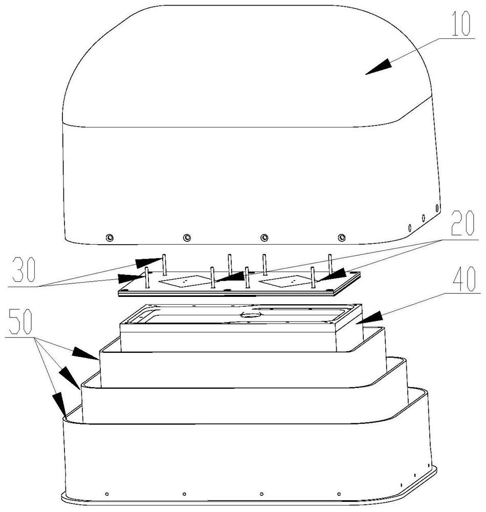
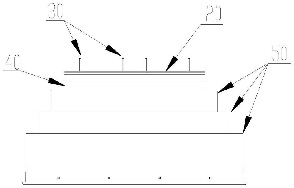
[0071] Such as figure 1 A schematic diagram of a three-dimensional decomposition structure of a shaped beam directional antenna provided by the present invention, figure 2 The schematic structural diagram of the front view of a shaped beam directional antenna provided by the present invention after removing the cover is shown as follows:

[0072] A shaped beam directional antenna is used for satellite navigation receivers to perform directional transmission and reception of satellite navigation signals, including:

[0073] Cover 10, patch antenna 20, monopole oscillator 30, antenna support structure 40 and three-dimensional metal choke slot 50, wherein:

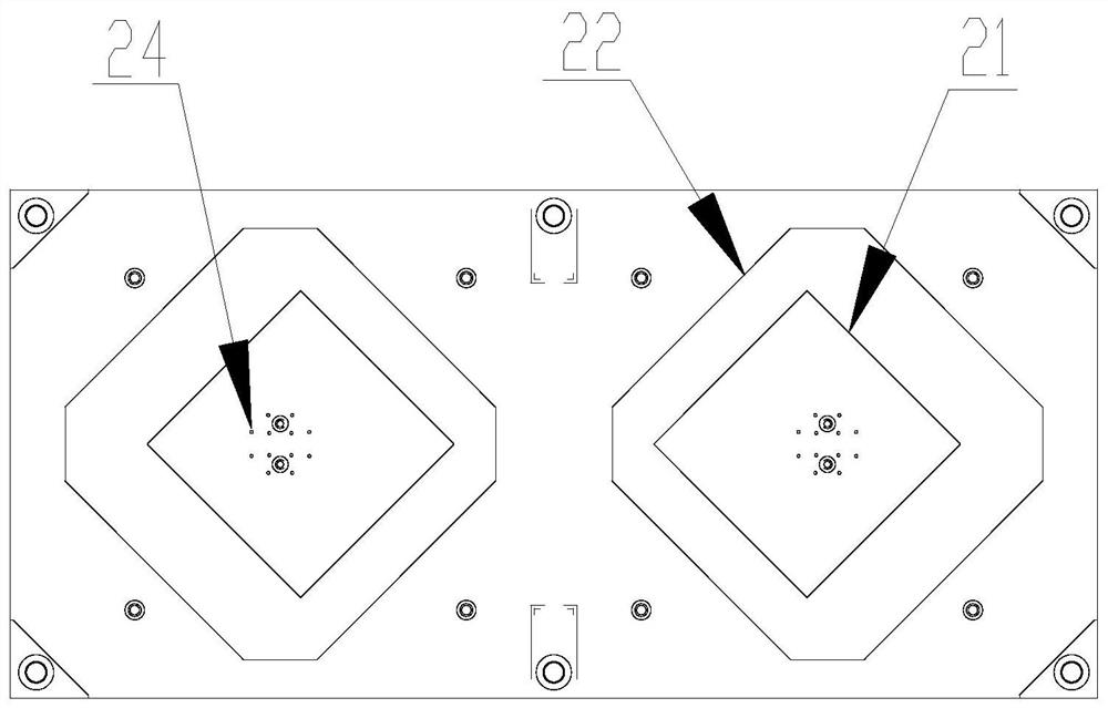
[0074] At least two patch antennas 20 are arranged symmetrically on a plane to form an antenna array;

[0075] A plurality of monopole oscillators 30 are installed on the antenna array to form a monopole array, and each monopole oscillator 30 is arranged along the periphery of the antenna array;

[0076] The antenna suppo...


PUM


Abstract

The invention discloses a shaped beam directional antenna. The shaped beam directional antenna comprises an antenna array formed by arranging at least two patch antennas on a plane, a monopole array formed by arranging a plurality of monopole oscillators along the periphery of the antenna array, and a choke groove structure body formed by arranging at least two three-dimensional metal choke grooves at intervals outside a metal barrel-shaped antenna supporting structure body in a sleeving manner, wherein the heights of the three-dimensional metal choke grooves forming the choke groove structure body are sequentially reduced from inside to outside and are lower than the height of the antenna supporting structure body, the antenna array is installed at the top part of the antenna supporting structure body, the monopole array, the antenna array and the choke groove structure body are covered with a cover shell, and the cover shell is fixed to the three-dimensional metal choke groove in the outermost layer of the choke groove structure body. The shaped beam directional antenna is used for dual-band transceiving orientation of satellite navigation signals by a satellite navigation receiver, has the quality characteristics of dual circular polarization, high and low elevation gain and high phase center precision, is compact in structure, high in integration level and convenient to assemble and use, and can meet the application requirements of special scenes.

Description

technical field [0001] The invention relates to an antenna, in particular to a shaped beam directional antenna, and belongs to the technical field of radio antenna equipment production. Background technique [0002] Antenna is a component used to transmit or receive electromagnetic waves. It is widely used in communication, broadcasting, television, radar, navigation, electronic countermeasures, remote sensing, radio astronomy and other engineering systems. In the information age, everything that uses electromagnetic waves to transmit information is Need to rely on the antenna to work. [0003] With the development of satellite navigation technology, the accuracy of radio positioning and navigation has been continuously improved. Correspondingly, higher requirements have been put forward for the quality and performance of the shaped beam directional antenna as the front end of the satellite navigation receiver. [0004] The shaped beam directional antenna as the front end o...

Claims


Application Information

Patent Timeline
Patent Type & Authority Applications(China)
IPC IPC(8): H01Q21/00H01Q1/12H01Q1/38H01Q1/52
CPCH01Q1/12H01Q1/38H01Q1/523H01Q1/528H01Q21/0006
Inventor 樊小景张楷生毛荟川穆桐
Owner 上海雷骥电子科技有限公司
Why Eureka
Try Eureka