Electrical and/or electronic component and contact system

a technology of electronic components and contact systems, applied in the direction of printed circuit non-printed electric components association, soldering apparatus,auxillary welding devices, etc., can solve problems such as poor welding or non-weld contact, visual hardly discernible, and source of malfunctioning defects

Pending Publication Date: 2022-08-25
ROBERT BOSCH GMBH
View PDF0 Cites 0 Cited by
  • Summary
  • Abstract
  • Description
  • Claims
  • Application Information

AI Technical Summary

Problems solved by technology

Additionally, poorly welded or non-welded contacts, in particular, are visually hardly discernible, and they may thus represent a source of defects for malfunctions.
In particular, in the case of very compact electronic circuits, a necessary space for such a device is not always present.
Furthermore, such a device is often difficult to handle since an access has to occur from both sides of the weld partners.

Method used


Image

  • Electrical and/or electronic component and contact system
  • Electrical and/or electronic component and contact system

Examples


Embodiment Construction

[0028]In the figures, functionally equivalent components are each denoted by identical reference numerals.

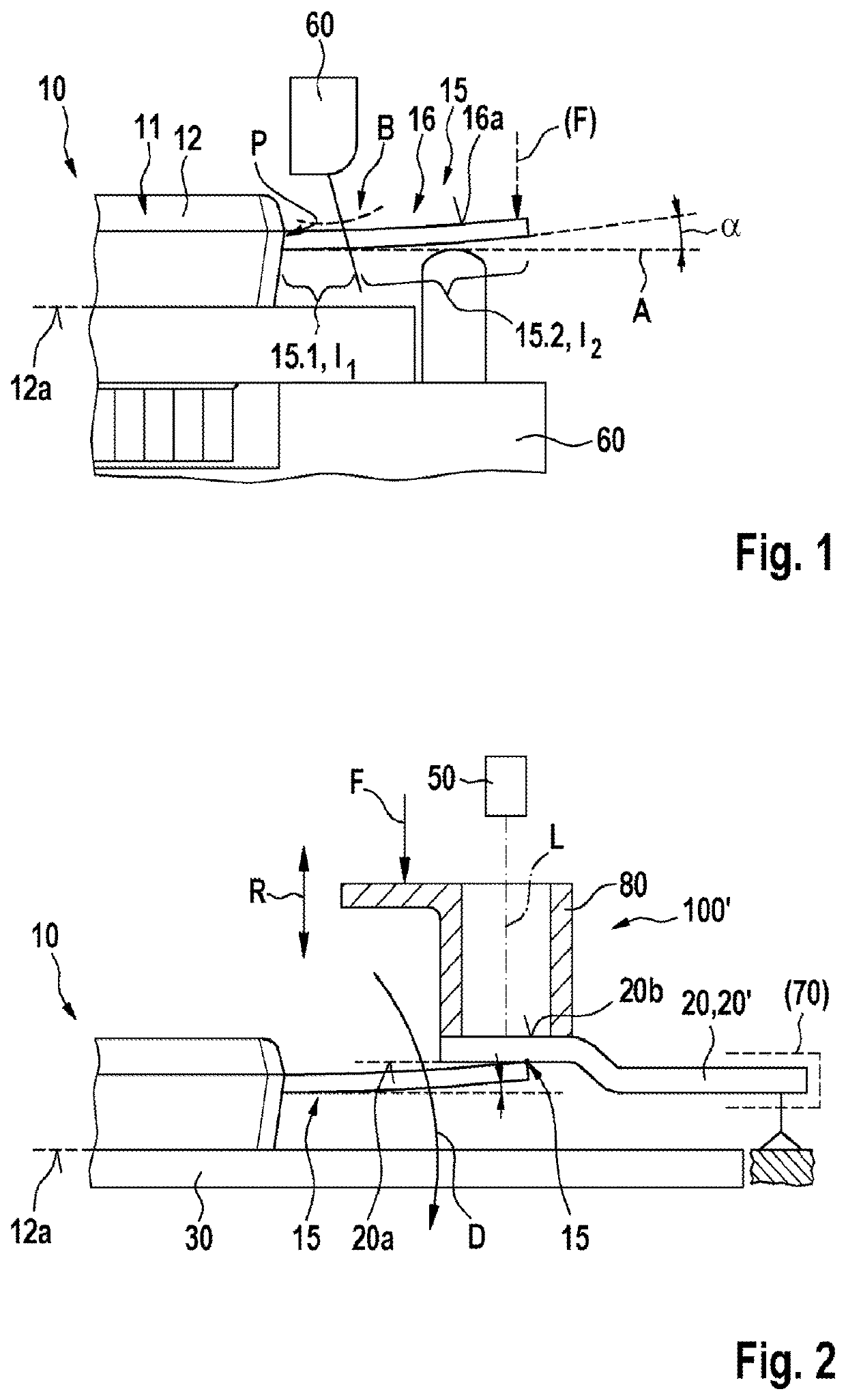
[0029]FIG. 1 shows an electrical and / or electronic component 10 in a side view. It includes an outside contact terminal 15, which is designed as a terminal lug attached at one side. The attachment takes place to a component base body 11, via which terminal lug 15 is contacted with an electrical functional area of component 10. Terminal lug 15 is formed of a sheet metal material by way of example, for example of a copper sheet. In the present exemplary embodiment, terminal lug 15 includes a bending point B and, via the longitudinal extension of terminal lug 15, thus sectionally divides the terminal lug at least into a longitudinal section I1 of a terminal leg 15.1 and an adjoining longitudinal section I2 of a bending leg 15.2. At its one end, terminal leg 15.1 is thus attached at one side to component base body 11 and opens via the other end, starting at bending point B, into the...


PUM

PropertyMeasurementUnit
compensating angleaaaaaaaaaa
gap widthaaaaaaaaaa

Abstract

An electrical and/or electronic component including at least one electrical outside connecting contact. This contact is a terminal lug, which is attached at one side, for the electrical contacting with a contacting partner. The terminal lug includes a connecting side including a planar connecting surface for the electrical contacting. The exposed end of the terminal lug includes a bending leg, which is bent out of the plane by a compensating angle toward the connecting side. The bending leg includes the connecting surface. The terminal lug is designed such that, when a contacting partner, which is planar at least in this area, makes site contact with the free end of the bending leg with a force applied from the connecting side, a position orientation of the connecting surface is adaptable counter to the compensating angle until a gap-free contact is made between the connecting surface and the planar contacting partner.

Description

FIELD[0001]The present invention relates to an electrical and / or electronic component, to a contact system including the electrical and / or electronic component, and to a method for forming the contact system.BACKGROUND INFORMATION[0002]It is generally conventional to establish a mechanical and an electrical connection of metallic workpieces with the aid of welding, for example with the aid of laser welding. This is used, among other things, when welding together power contacts of power modules within electronic power circuits, for example. In the process, the two weld partners, for example the power contact and a connecting point of the electronic circuit, have to be brought together very closely, in general below a gap width of 100 μm. If gap distances are larger, metallic spatter may otherwise occur during laser welding, all the way to non-welded contacts. Additionally, poorly welded or non-welded contacts, in particular, are visually hardly discernible, and they may thus represen...

Claims


Application Information

Patent Timeline
Patent Type & Authority Applications(United States)
IPC IPC(8): H01L23/495H05K1/18H01L21/48H05K3/32
CPCH01L23/49524H05K1/18H01L21/4825H05K3/328H05K2201/1078H05K2201/10916H05K2201/10833H01L23/3107H01R13/02H01R43/0221H01L23/49555H01R12/716B23K26/22H01L23/49517B23K26/244B23K26/26B23K26/32B23K37/0443B23K2101/36H05K2203/107
Inventor SUENNER, THOMASSCHIELE, CHRISTIANHEMMERT, REINER
Owner ROBERT BOSCH GMBH
Why Eureka
Try Eureka