Aircraft propulsion system

a propulsion system and aircraft technology, applied in the direction of machines/engines, gas turbine power plants, mechanical equipment, etc., can solve the problems of inability to rapidly reduce the the engine will not be able to rapidly reduce the output, and the engine will not be able to quickly so as to reduce the output and reduce the output of an engine. rapid

Pending Publication Date: 2022-09-15
HONDA MOTOR CO LTD
View PDF0 Cites 2 Cited by
  • Summary
  • Abstract
  • Description
  • Claims
  • Application Information

AI Technical Summary

Benefits of technology

[0012]According to (1) to (5), it is possible to rapidly reduce an output of an gas turbine engine while preventing an engine misfire through an aircraft propulsion system including: the gas turbine engine attached to an airframe of an aircraft; a generator connected to an engine shaft of the gas turbine engine; a first electric motor driven using electric power including electric power generated by the generator; a rotor attached to the airframe of the aircraft and driven using a driving force output by the first electric motor; and a control device configured to control an operating state of the gas turbine engine, wherein the control device includes a flow rate controller which reduces the flow rate of fuel supplied to the gas turbine engine so that the gas turbine engine does not misfire when a decrease in output of the gas turbine engine is promoted using a driving force output by a second electric motor included in the generator, and a drive controller which controls the magnitude of the driving force output by the second electric motor so that the temperature of the gas turbine engine does not exceed an allowable temperature when the driving force output by the second electric motor promotes a decrease in output of the gas turbine engine.

Problems solved by technology

However, when the engine output is reduced, there is a concern concerning an engine misfire if an amount of fuel supply is not appropriately controlled.
If the engine output is slowly reduced in an attempt to prevent an engine misfire, fuel will be wasted accordingly.
For this reason, in the related art, there is a case in which it is not possible to rapidly reduce an engine output while preventing an engine misfire.

Method used


Image

  • Aircraft propulsion system
  • Aircraft propulsion system
  • Aircraft propulsion system

Examples


Embodiment Construction

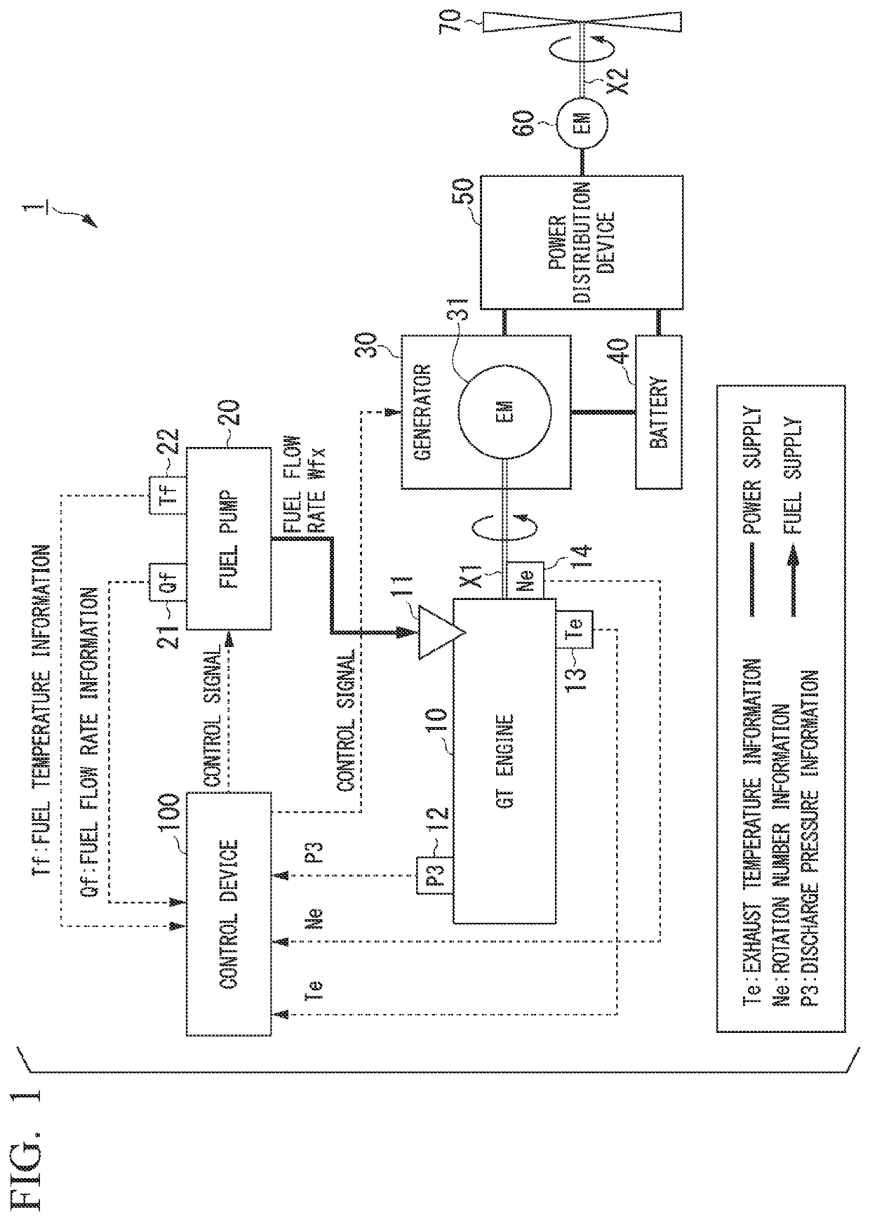
[0019]An aircraft propulsion system according to the present invention will be described below with reference to the drawings. As used throughout this disclosure, the singular forms “a,”“an,” and “the” include plural reference unless the context clearly dictates otherwise. FIG. 1 is a diagram showing an example of a constitution of an aircraft propulsion system 1 according to an embodiment. The aircraft propulsion system 1 includes, for example, a gas turbine engine (GT engine) 10, a fuel pump 20, a generator 30, a battery 40, a power distribution device 50, a motor 60, a rotor 70, and a control device 100.

[0020]The GT engine 10 includes, for example, an intake port (not shown), a compressor, a combustion chamber, a turbine, and the like. The compressor compresses intake air suctioned through the intake port. The combustion chamber is located downstream of the compressor and a gas obtained by mixing the compressed air with fuel is burned to generate combustion gas in the combustion ...


PUM


Abstract

An aircraft propulsion system includes: a gas turbine engine attached to an airframe of an aircraft; a generator connected to an engine shaft of the engine; a first electric motor driven using electric power including electric power generated by the generator; a rotor attached to the airframe of the aircraft and driven using a driving force output by the first electric motor; and a control device configured to control an operating state of the engine. The control device includes a flow rate controller which reduces the flow rate of fuel supplied to the engine so that the engine does not misfire when a decrease in output of the engine is promoted using a driving force output by a second electric motor included in the generator, and a drive controller which controls the magnitude of the driving force output by the second electric motor so that the temperature of the engine does not exceed an allowable temperature.

Description

CROSS-REFERENCE TO RELATED APPLICATION[0001]Priority is claimed on Japanese Patent Application No. 2021-040377, filed Mar. 12, 2021, the content of which is incorporated herein by reference.BACKGROUNDField of the Invention[0002]The present invention relates to an aircraft propulsion system.Description of Related Art[0003]In the related art, there is an aircraft engine hybrid propulsion device composed of a gas turbine engine, a generator, a battery, and a motor (the specification of U.S. Pat. No. 8,727,271). Generally, in the operation of such an aircraft engine hybrid propulsion device, although it is possible to shift a takeoff mode in which a high load is applied to an engine to a cruise mode in which a low load is applied to the engine, at that time, rapidly reducing an engine output is required from the viewpoint of fuel efficiency, thrust, operability associated with battery charging, and the like.SUMMARY[0004]However, when the engine output is reduced, there is a concern conc...

Claims


Application Information

Patent Timeline
Patent Type & Authority Applications(United States)
IPC IPC(8): F01D15/10B64D27/24B64D27/10
CPCF01D15/10B64D27/24B64D27/10B64D2027/026F02K5/00F05D2220/76F05D2270/303F05D2270/06F02C9/28F05D2270/3032F05D2220/323
Inventor OTA, AKIRA
Owner HONDA MOTOR CO LTD
Why Eureka
Try Eureka