Acoustic device and electronic apparatus

a technology of electronic equipment and acoustic device, which is applied in the field of acoustics, can solve the problems of affecting the use life, and affecting the acoustic performance of the speaker uni

Pending Publication Date: 2022-09-15
GOERTEK INC
View PDF0 Cites 0 Cited by
  • Summary
  • Abstract
  • Description
  • Claims
  • Application Information

AI Technical Summary

Problems solved by technology

Due to the volume limitation of the cavity in the acoustic system, it is difficult for the acoustic system, especially the small acoustic system, to achieve the effect of satisfactorily reproducing the bass.
However, the above two methods have problems, the first method of adding the sound-absorbing material in the housing needs to realize good sealing and packaging of the sound-absorbing material, otherwise if the sound-absorbing material enters the speaker unit, it will damage the acoustic performance of the speaker unit and affect the usage life of the speaker unit; in the second method of adopting passive radiator, near the resonance frequency point fp, the passive radiator radiates strongly and the sound generating unit almost stops, therefore, the local sensitivity enhancement of the acoustic system can be realized in the frequency band near fp through the high sensitivity design of the passive radiator, however, in the frequency band below fp, the phase of the sound wave of the passive radiator is opposite to the phase of the sound wave of the sound generating unit, and the sound waves offset with each other, and thus the passive radiator has a negative effect on the sensitivity of the acoustic system.
In short, the passive radiator can only improve the sensitivity of the frequency band near the resonance point, but cannot improve all the low frequency bands.
Secondly, if the air permeable micropores is provided with too large area, liquid and impurities in the external environment, that is, the second sealed cavity will continuously adhere to the flexible deformation part and affect the performance and the usage lifespan of the flexible deformation part.
This is usually solved by the method of attaching a dustproof mesh cloth onto the protective cover plate, but this method may increase material costs and assembly process, and the arrangement of the dustproof mesh cloth may increase the space of the product in Z-axis.

Method used


Image

  • Acoustic device and electronic apparatus
  • Acoustic device and electronic apparatus
  • Acoustic device and electronic apparatus

Examples


embodiment 1

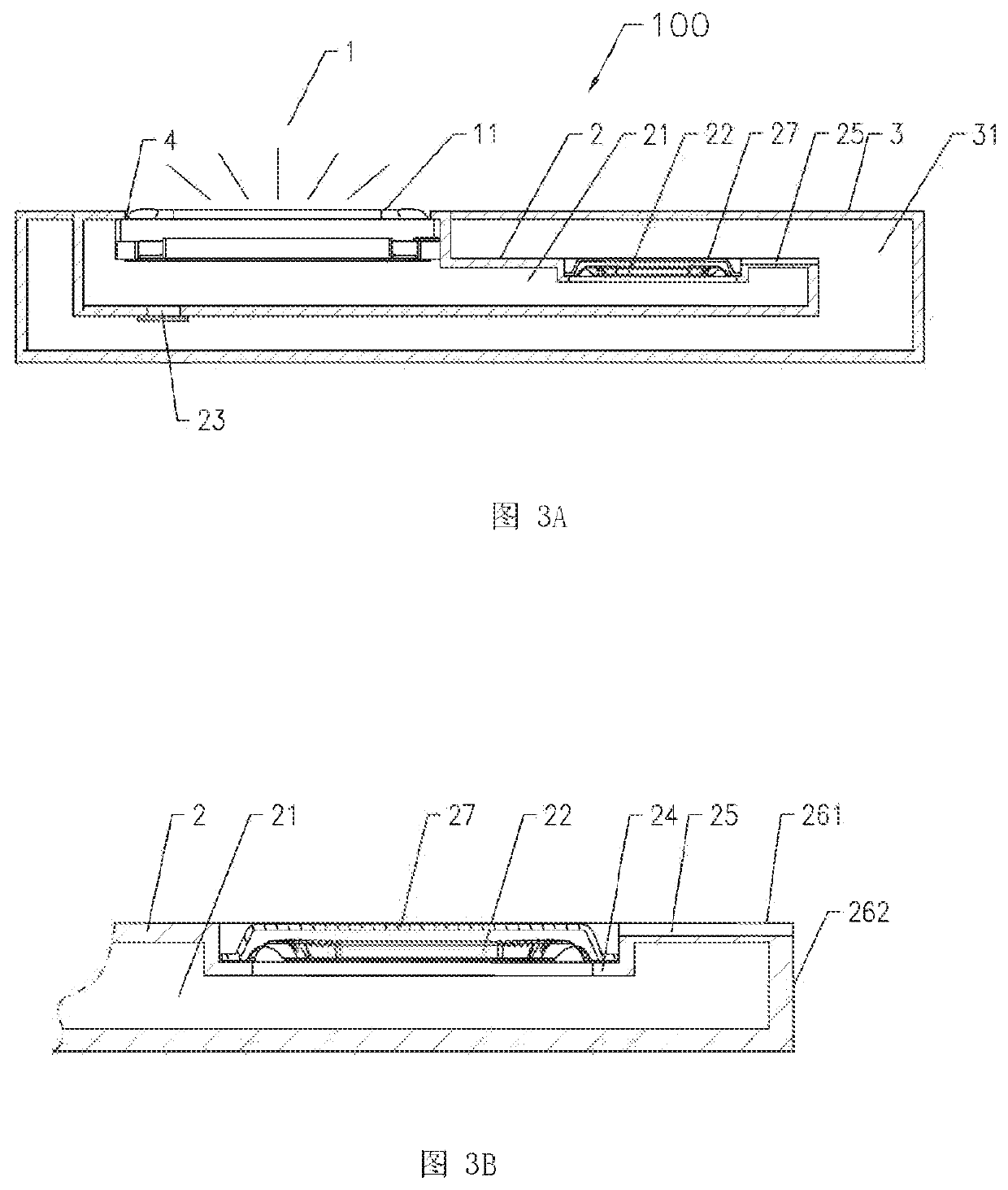
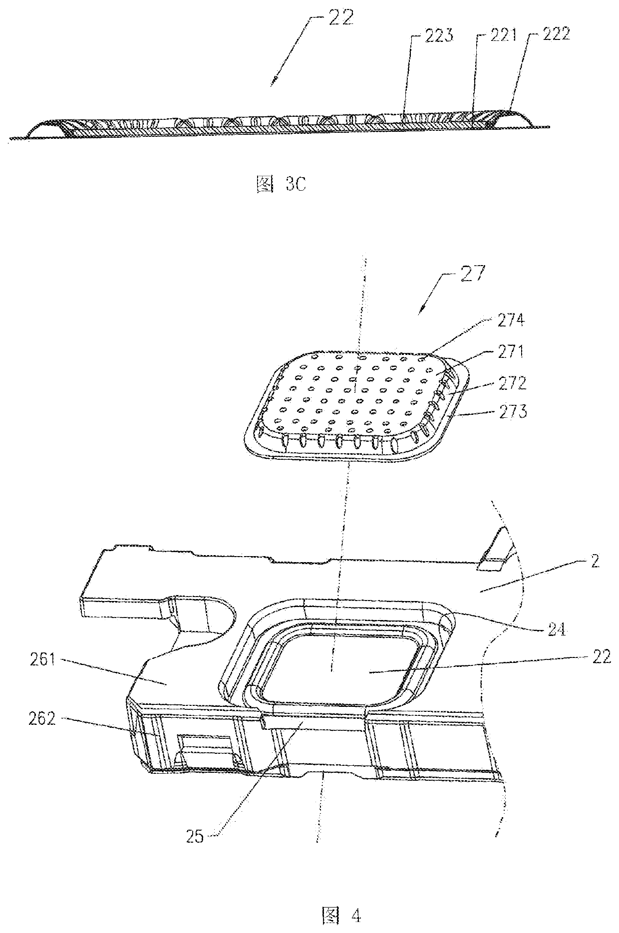
[0048]As shown in FIGS. 3A-4, an acoustic device comprises a sound generating unit 1. In this embodiment, the sound generating unit 1 is a micro sound generating unit, and more specifically, the sound generating unit 1 is a micro moving coil speaker. The sound generating unit 1 generally comprises a housing, and a vibrating system and a magnetic circuit system accommodated and fixed in the housing. The vibrating system comprises a vibrating diaphragm 11 fixed on the housing and a voice coil combined with the vibrating diaphragm 11. A magnetic gap is formed in the magnetic circuit system. The voice coil is provided in the magnetic gap. After alternating current is supplied to the voice coil, the voice coil moves up and down in the magnetic field, thus driving the vibrating diaphragm 11 to vibrate and generate sound.

[0049]The acoustic device is provided with a sound outlet 4, the sound wave at the front side of the vibrating diaphragm 11 radiates to the outside through the sound outle...

embodiment 2

[0085]The main difference between this embodiment and the above embodiment is that: in this embodiment, a plurality of sound generating units 1 and a plurality of first sealed cavities 21 are provided in a one-to-one correspondence, one second sealed cavity 31 is provided, and the cavity wall of each of the first sealed cavities 21 is provided with one flexible deformation part 22 and one protective cover plate 27. Specifically, the acoustic device in this embodiment comprises two sound generating units 1, in the meanwhile, two first sealed cavities 21 are provided and designed correspondingly, one second sealed cavity 31 is provided, and the cavity wall of each of the two first sealed cavities 21 is provided and designed with a flexible deformation part 22 and a protective cover plate 27. This design can facilitate the application in the case of acoustic devices or systems requiring a plurality of sound generating units 1, for example, the design requirements of stereo or array for...

embodiment 3

[0087]This embodiment discloses an electronic apparatus 5, as shown in FIG. 7, the acoustic device 100 in the above embodiments is mounted on the electronic apparatus 5. The electronic apparatus 5 may be a mobile phone, tablet computer, notebook computer, etc.

[0088]The electronic apparatus 5 specifically comprises a housing of the electronic apparatus, and at least a part of the housing of the electronic apparatus is used to form the first sealed cavity 21 and / or the second sealed cavity 31 of the acoustic device. That is, part or entire of the cavity walls of the first sealed cavity 21 are composed of the housing of the electronic apparatus, or part or entire of the cavity walls of the second sealed cavity 31 are composed of the housing of the electronic apparatus, or part or entire of the cavity walls of the first sealed cavity 21 and the second sealed cavity 31 are composed of the housing of the electronic apparatus. In the present invention, the housing of the electronic apparat...


PUM


Abstract

Disclosed is an acoustic device, comprising a sound generating unit, a sound wave at a front side of the vibrating diaphragm radiates to outside through the sound outlet, a first sealed cavity is formed at a rear side of the vibrating diaphragm, a cavity wall of the first sealed cavity is provided with a mounting hole, a flexible deformation part is provided at the mounting hole, the second sealed cavity encloses a sound wave, in the second sealed cavity, a protective cover plate located at outside of the flexible deformation part is further provided on the mounting hole, and an escape space used for avoiding vibration of the flexible deformation part is formed between the protective cover plate and the flexible deformation part; air permeable micropores are provided on the protective cover plate, the air permeable micropores have an area less than or equal to 0.2 mm2.

Description

TECHNICAL FIELD[0001]The present invention relates to the acoustics technical field, in particular, relates to an acoustic device and an electronic apparatus in which the acoustic device is mounted.BACKGROUND ART[0002]Generally, an acoustic system with a traditional structure (Prior Art 1) comprises a closed housing and a sound generating unit provided on the closed housing, and a cavity is formed between the closed housing and the sound generating unit. Due to the volume limitation of the cavity in the acoustic system, it is difficult for the acoustic system, especially the small acoustic system, to achieve the effect of satisfactorily reproducing the bass. Conventionally, in order to achieve satisfactory bass reproduction in the acoustic system, two methods are often used, one of them is to provide a sound-absorbing material (such as activated carbon, zeolite, etc.) in the housing of the acoustic system to adsorb or desorb the gas in the housing, so as to increase the volume and t...

Claims


Application Information

Patent Timeline
Patent Type & Authority Applications(United States)
IPC IPC(8): H04R1/02H04R1/28
CPCH04R1/021H04R1/2811H04R1/2849H04R2499/11H04R1/2888H04R1/023H04R1/086H04R1/44
Inventor CHEN, ALIANGCHEN, GUOQIANGLI, ZHAOPENG
Owner GOERTEK INC
Why Eureka
Try Eureka