Method of treating a coated cutting tool

a cutting tool and coating technology, applied in the direction of superimposed coating process, manufacturing tools, coatings, etc., can solve the problems of reducing the risk of reducing the stress in the surface area and the reducing the edge line chipping resistan

Pending Publication Date: 2022-09-22
SANDVIK COROMANT
View PDF7 Cites 0 Cited by
  • Summary
  • Abstract
  • Description
  • Claims
  • Application Information

AI Technical Summary

Benefits of technology

[0009]It has surprisingly been found that there is an optimum in the performance of a cutting tool if the laser shock peening is performed with the settings of the LSP energy density within 0.4 to 1.6 J / mm2, preferably within 0.9 to 1.4 J / mm2. If the LSP energy density is too low the impact from the LSP is too low to result in an improved edge line toughness or wear resistance. If the LSP energy density is too high there is a higher risk of reduced stresses in the surface area and thereby a reduced edge line chipping resistance.
[0011]In one embodiment of the present invention a black paint or a black tape is applied to the coated cutting tool prior to applying LSP. An advantage with the usage of a black paint or a black tape is that the coating underneath can be kept without any decrease in thickness or change in appearance.
[0012]In one embodiment of the present invention the coating comprises an outer layer of one or more of TiN, TiCN, TiC, TiB2, ZrCN, TiAlN or TiSiN. These layers can be used as the absorption layer instead of a paint or a tape. An advantage with these layers is that they can be deposited as part of the CVD or PVD coating, and thus an extra step of applying a black tape or paint can be avoided. A further advantage is that the effect of the LSP seems to be more pronounced using these layers, inducing a higher level of residual stress in the surface area of the substrate.
[0013]In one embodiment of the present invention the thickness of the outer layer is preferably 2-5 μm. If the thickness of the outer layer is to thin, a wear resistant layer beneath will be reduced in thickness during the LSP. If the thickness is larger than 5 μm the induces residual stresses in the substrate are less and therefore improvement from LSP on tool life becomes less pronounced.
[0020]In one embodiment of the present invention the LSP step is followed by a blasting, polishing and / or brushing step, preferably a blasting step such as shot blasting. Advantages with blasting, polishing and brushing are that the surface of the cutting tool can be finished by any of these techniques and thereby the cutting performance of the cutting tool can be improved. Shot blasting is advantageous since both the surface roughness and the residual stress level in the coating can be influenced, a lower surface roughness and a reduced tensile stress level or a higher compressive stress level can be achieved in the coating, such that the cutting tool life time can be extended.
[0030]In one embodiment of the present invention the peak power density of the laser during the LSP step is within 3 to 7 GW / mm2, preferably about 6 GW / mm2. This level of peak power density can be varied by varying either of the frequency, the pulse length, the effect of the laser or the spot size. A peak power density of within 3 to 7 GW / mm2 is advantageous in that the resulting peak pressure is high and thereby providing an improvement on the life time of the cutting tool.

Problems solved by technology

If the LSP energy density is too high there is a higher risk of reduced stresses in the surface area and thereby a reduced edge line chipping resistance.

Method used


Image

  • Method of treating a coated cutting tool
  • Method of treating a coated cutting tool
  • Method of treating a coated cutting tool

Examples


Embodiment Construction

[0042]Exemplifying embodiments of the present invention will now be disclosed in more detail and compared to comparative embodiments. Coated cutting tools (inserts) were prepared, analyzed and evaluated in cutting tests.

Substrate

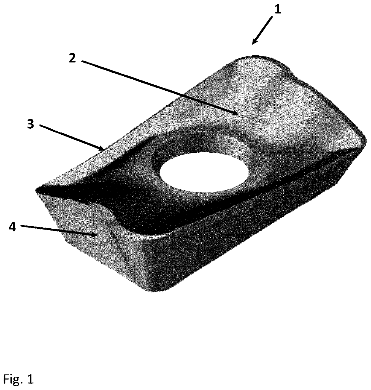
[0043]Cemented carbide substrates of ISO-type R390-11T308M-PM for milling were manufactured, see FIG. 1.

[0044]Two different cemented carbide compositions were manufactured. Substrate A was manufactured from a powder mixture with a composition of about 13.50 wt % Co, 0.57 wt % Cr and balance WC. Substrate B was manufactured from a powder mixture with a composition of about 9.14 wt % Co, 1.15 wt % Ta, 0.27 wt % Nb, 0.05 wt % Ti and balance WC. The powder mixtures was milled, dried, pressed into green bodies and sintered at 1450° C. to form sintered cemented carbide substrates.

Coating

[0045]CVD coatings were deposited on the two cemented carbide compositions. The CVD coating was composed of an inner TiN layer of 0.5 μm in thickness, a subsequent wear resistant T...


PUM

PropertyMeasurementUnit
wave lengthaaaaaaaaaa
thicknessaaaaaaaaaa
total thicknessaaaaaaaaaa

Abstract

A method of treating a coated cutting tool using laser shockpeening (LSP) is provided. The coated cutting tool includes a substrate and a coating, wherein the substrate is of cemented carbide or cermet. The coating includes a CVD layer and / or a PVD layer. The method includes the step of applying LSP to at least a portion of the cutting tool, wherein the LSP energy density is within 0.4 to 1.6 J / mm2 and wherein the LSP applies laser pulses to the at least one portion of the cutting tool.

Description

TECHNICAL FIELD[0001]The present invention relates to laser shock peening of coated cutting tools, wherein the cutting tool has a substrate of cermet or cemented carbide and a coating comprising layers made by CVD and / or PVD.BACKGROUND[0002]Cermet and cemented carbide are materials composed of hard constituents in a metallic binder. These materials are common substrates in cutting tools with properties such as high hardness, high resistance to wear, high toughness. These substrates are usually coated with a wear resistant coating such as a CVD coating of layers of for example TiCN and alumina or a PVD coating with layers of for example TiN and TiAlN.[0003]The coated cutting tools are usually treated with a surface treatment to improve its life time in cutting further. Common surface treatments are brushing to smoothen the outer surface or shaping the cutting edge, shot blasting to smoothen the surface and also to influence the residual stress levels in the surface area of the cement...

Claims


Application Information

Patent Timeline
Patent Type & Authority Applications(United States)
IPC IPC(8): C23C28/04C23C16/34C23C16/56C23C30/00
CPCC23C28/044C23C28/042C23C16/34C23C16/56C23C30/005B23K26/356C23C16/36C23C16/403B23K26/0622
Inventor SLAIWA, WARKAYUSSEFIAN, NIMA ZARIFPAULSRUD, GABRIEL
Owner SANDVIK COROMANT
Why Eureka
Try Eureka