Methods for forming ionically conductive polymer composite interlayers in solid-state batteries

a technology of ionically conductive polymer and composite interlayers, which is applied in the manufacture of electrodes, cell components, electrochemical generators, etc., can solve the problems of comparatively low power capability of solid-state batteries

Pending Publication Date: 2022-10-27
GM GLOBAL TECH OPERATIONS LLC
View PDF3 Cites 0 Cited by
  • Summary
  • Abstract
  • Description
  • Claims
  • Application Information

AI Technical Summary

Benefits of technology

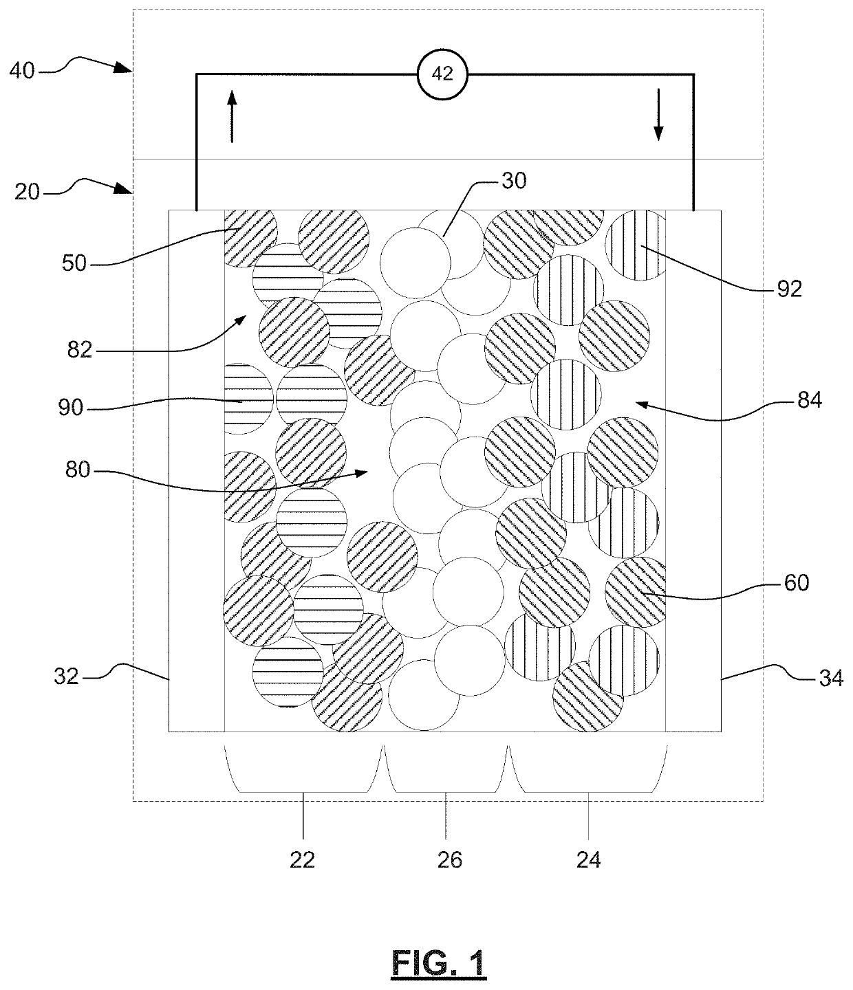
[0004]Solid-state batteries have advantages over batteries that include a separator and a liquid electrolyte. These advantages can include a longer shelf life with lower self-discharge, simpler thermal management, a reduced need for packaging, and the ability to operate within a wider temperature window. For example, solid-state electrolytes are generally non-volatile and non-flammable, so as to allow cells to be cycled under harsher conditions without experiencing diminished potential or thermal runaway, which can potentially occur with the use of liquid electrolytes. However, solid-state batteries generally experience comparatively low power capabilities. For example, such low power capabilities may be a result of interfacial resistance within the solid-state electrodes and / or at the electrode and solid-state electrolyte layer interfacial resistance caused by limited contact, or void spaces, between the solid-state electroactive particles and / or the solid-state electrolyte particles; or reactions between the solid-state electrodes and the solid-state electrolyte layer. Accordingly, it would be desirable to develop high-performance solid-state battery designs, materials, and methods that improve power capabilities, as well as energy density.SUMMARY

Problems solved by technology

However, solid-state batteries generally experience comparatively low power capabilities.

Method used


Image

  • Methods for forming ionically conductive polymer composite interlayers in solid-state batteries
  • Methods for forming ionically conductive polymer composite interlayers in solid-state batteries
  • Methods for forming ionically conductive polymer composite interlayers in solid-state batteries

Examples


example 1

[0098]An example electrode may be prepared in accordance with various aspects of the present disclosure. The example cell may include a solid-state electrolyte layer disposed between a first electrode (e.g., first lithium-metal electrode) and a second electrode (e.g., second lithium-metal electrode). The first electrode may include a first electroactive material layer (that includes, for example, a lithium metal) disposed on or adjacent to a first current collector (that includes, for example, copper). The second electrode may include a second electroactive material layer (that includes, for example, a lithium metal) disposed on or adjacent to a second current collector (that includes, for example, copper). The first electroactive material layer and the second electroactive material layer may be substantially aligned with the solid-state electrolyte layer. For example, the first electroactive material layer may be substantially aligned with a first surface of the solid-state electro...

example 2

[0102]An example electrode may be prepared in accordance with various aspects of the present disclosure. The example cell may include a solid-state electrolyte layer disposed between a first electrode (e.g., first lithium-metal electrode) and a second electrode (e.g., second lithium-metal electrode). The first electrode may include a first electroactive material layer (that includes, for example, a lithium metal) disposed on or adjacent to a first current collector (that includes, for example, copper). The second electrode may include a second electroactive material layer (that includes, for example, a lithium metal) disposed on or adjacent to a second current collector (that includes, for example, copper). The first electroactive material layer and the second electroactive material layer may be substantially aligned with the solid-state electrolyte layer. For example, the first electroactive material layer may be substantially aligned with a first surface of the solid-state electro...


PUM

PropertyMeasurementUnit
ionic conductivityaaaaaaaaaa
pressureaaaaaaaaaa
thicknessaaaaaaaaaa

Abstract

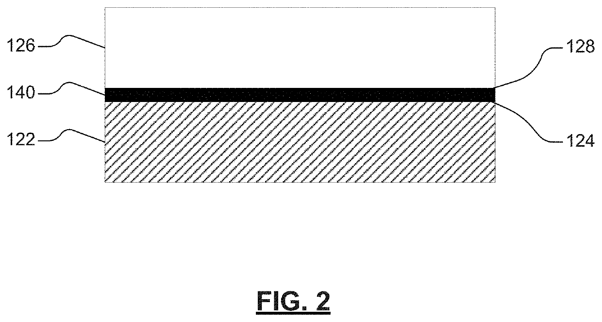
The present disclosure provides a method for forming an ionically conductive polymer composite interlayer. The method may include forming a precursor layer between a first surface of an electroactive material layer and a first surface of a solid-state electrolyte layer and converting the precursor layer to the ionically conductive polymer composite interlayer. The at least one of the electroactive material layer or solid-state electrolyte may include lithium. The first surface of the electroactive material layer and the first surface of the solid-state electrolyte layer may be substantially parallel. The precursor layer may include one or more fluoropolymers comprising carbon and fluorine. The ionically conductive polymer composite layer may have an ionic conductivity greater than or equal to about 1.0×10⁻⁸ S·cm−1 to less than or equal to about 1.0 S·cm−1 and may include a lithium fluoride embedded in a carbonaceous matrix.

Description

GOVERNMENT FUNDING[0001]This invention was made with government support under Agreement No. DE-EE-0008863 awarded by the Department of Energy. The Government may have certain rights in the invention.INTRODUCTION[0002]This section provides background information related to the present disclosure which is not necessarily prior art.[0003]Electrochemical energy storage devices, such as lithium-ion batteries, can be used in a variety of products, including automotive products such as start-stop systems (e.g., 12V start-stop systems), battery-assisted systems (“μBAS”), Hybrid Electric Vehicles (“HEVs”), and Electric Vehicles (“EVs”). Typical lithium-ion batteries include two electrodes and an electrolyte component and / or separator. One of the two electrodes can serve as a positive electrode or cathode, and the other electrode can serve as a negative electrode or anode. Lithium-ion batteries may also include various terminal and packaging materials. Rechargeable lithium-ion batteries opera...

Claims


Application Information

Patent Timeline
Patent Type & Authority Applications(United States)
IPC IPC(8): H01M10/0562H01M4/36H01M4/38H01M4/62H01M4/583H01M4/04
CPCH01M10/0562H01M4/362H01M4/382H01M4/623H01M4/583H01M4/0471H01M10/058H01M2300/0082H01M2300/0094Y02E60/10
Inventor XIAO, XINGCHENGCHEN, MENGYUAN
Owner GM GLOBAL TECH OPERATIONS LLC
Why Eureka
Try Eureka