
Space Weather Monitor System

Pending Publication Date: 2022-11-17
RGT UNIV OF MICHIGAN
View PDF0 Cites 0 Cited by
  • Summary
  • Abstract
  • Description
  • Claims
  • Application Information

AI Technical Summary

Benefits of technology

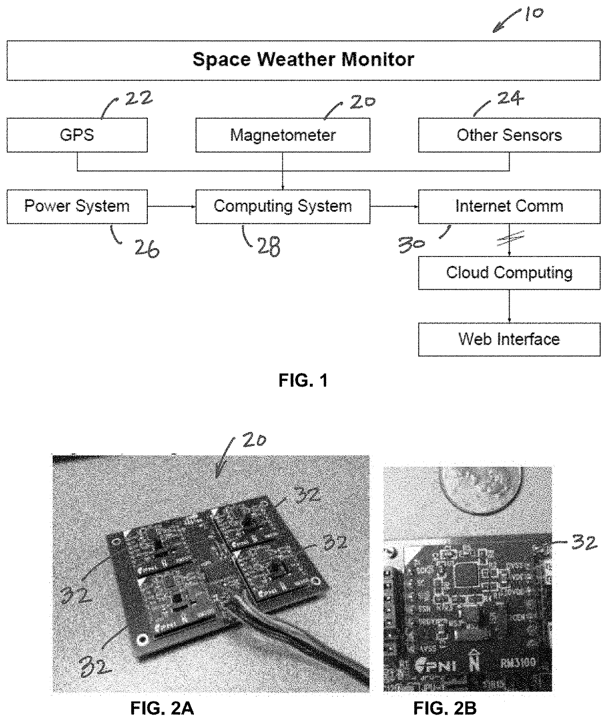
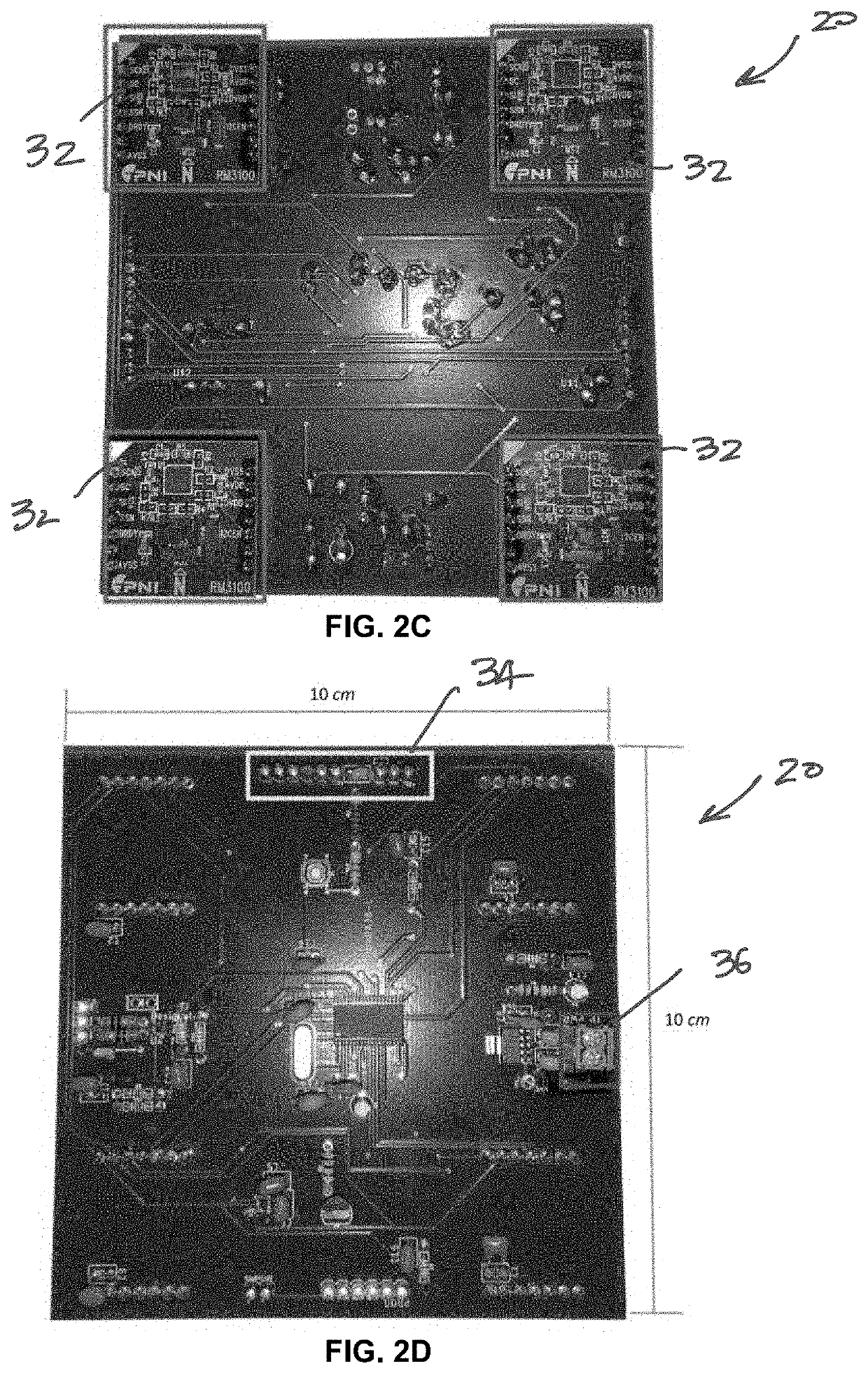
The present invention is a new research magnetometer system that allows for the deployment of low-cost and dense arrays of magnetometers at mid and auroral latitudes to monitor space weather. This system is designed to remove some of the barriers of current instrument deployment, including the need for an isolated building with power and communication, drilling holes, and burying sensor cable. The invention also utilizes low-cost commercial systems and the Internet-of-Things to enable a wider ecosystem of magnetometer arrays and potentially citizen scientists. The technical effects of this invention include reducing the cost and complexity of space weather monitoring and expanding the geographic coverage and density of meteorological observations.

Problems solved by technology

There are significant variations in space weather effects depending on latitude, longitude, and local time, but they have not been well studied due to the sparsity of ground-based instrumentation even in relatively well instrumented areas of the globe.

Method used


Image

  • Space Weather Monitor System
  • Space Weather Monitor System
  • Space Weather Monitor System

Examples


Embodiment Construction

[0024]Example embodiments will now be described more fully with reference to the accompanying drawings.

[0025]Example embodiments are provided so that this disclosure will be thorough, and will fully convey the scope to those who are skilled in the art. Numerous specific details are set forth such as examples of specific components, devices, and methods, to provide a thorough understanding of embodiments of the present disclosure. It will be apparent to those skilled in the art that specific details need not be employed, that example embodiments may be embodied in many different forms and that neither should be construed to limit the scope of the disclosure. In some example embodiments, well-known processes, well-known device structures, and well-known technologies are not described in detail.

[0026]The terminology used herein is for the purpose of describing particular example embodiments only and is not intended to be limiting. As used herein, the singular forms “a,”“an,” and “the” ...


PUM


Abstract

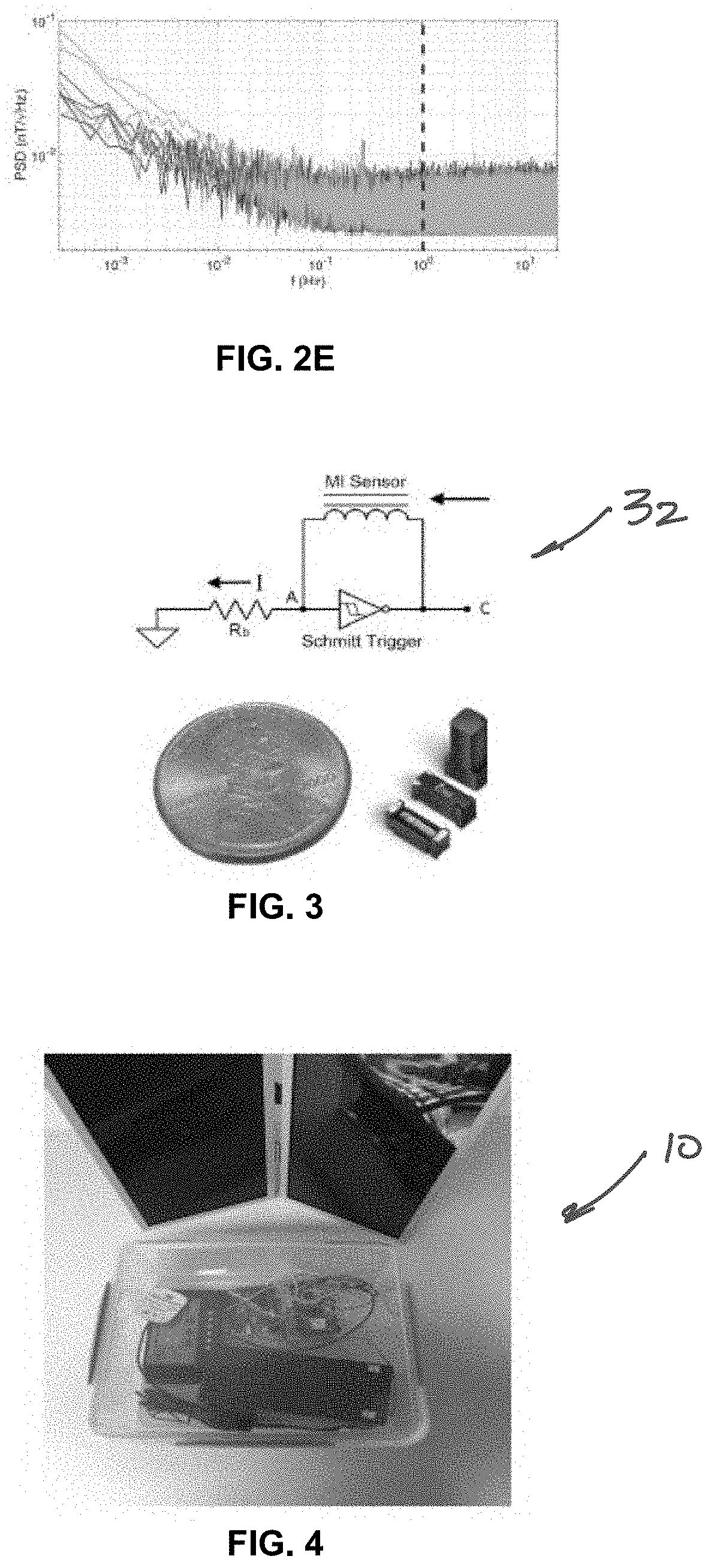
A magneto-inductive DC magnetometer is provided that is operable to output fluxgate quality measurements in a low mass, volume, power and cost package. The magnetometer enables constellation-class missions not only due to its low-resource requirements, but also due to its potential for commercial integrated circuit fabrication. In addition, the magnetometer will be part of a ground-based Space Weather Underground Citizen Science instrument package that enables dense arrays of space weather-relevant observations at mid-latitudes. The magneto-inductive operating principle is based on a simple resistance-inductor (RL) circuit and involves measurement of the time it takes to charge and discharge the inductor between an upper and lower threshold by means of a Schmitt trigger oscillator. This time is proportional to the inductance that in turn is proportional to the field strength.

Description

CROSS-REFERENCE TO RELATED APPLICATIONS[0001]This application claims the benefit of U.S. Provisional Application No. 63 / 187,099 filed on May 11, 2021. The entire disclosure of the above application is incorporated herein by reference.GOVERNMENT INTEREST[0002]This invention was made with government support under AGS1848724 awarded by the National Science Foundation. The government has certain rights in the invention.FIELD[0003]The present disclosure relates to weather monitoring and, more particularly, relates to a space weather monitor system.BACKGROUND AND SUMMARY[0004]This section provides background information related to the present disclosure which is not necessarily prior art. This section provides a general summary of the disclosure, and is not a comprehensive disclosure of its full scope or all of its features.[0005]Space weather refers to the dynamics of the Earth's space environment due to solar disturbances that directly impact technological systems, such as satellite nav...

Claims


Application Information

Patent Timeline
IPC IPC(8): G01R33/02G01C21/24G01W1/10
CPCG01R33/0206G01C21/24G01W1/10Y02A90/10G01R33/0094G01R33/0005G01R33/028G01R33/0041
Inventor MOLDWIN, MARK B.OJEDA, LAURO V.
Owner RGT UNIV OF MICHIGAN
Learn More