Semiconductor device with salicide structure and fabrication method thereof

a technology of silicide and semiconductor devices, which is applied in the direction of semiconductor devices, electrical devices, transistors, etc., can solve the problems of reducing the drawing speed of electrons, affecting the operation speed of the inner circuit of the lsis, and difficult production of refractory silicides

Inactive Publication Date: 2000-03-14
NEC ELECTRONICS CORP
View PDF11 Cites 76 Cited by
  • Summary
  • Abstract
  • Description
  • Claims
  • Application Information

AI Technical Summary

Problems solved by technology

However, the decrease in the length of the gate electrodes and the width of the source / drain regions increases their electric resistance and as a result, there arises a problem that the operation speed of the inner circuits of the LSIs tends to be badly affected.
In this case, however, there is a problem that refractory silicide tends to be difficult to be produced if arsenic (As) is used as the n-type impurity for the source / drain regions 114.
This lowers the drawing speed of the electrons from the floating gates 108, thereby delaying the operation speed of the memory device.

Method used


Image

  • Semiconductor device with salicide structure and fabrication method thereof
  • Semiconductor device with salicide structure and fabrication method thereof
  • Semiconductor device with salicide structure and fabrication method thereof

Examples


first embodiment

A flush nonvolatile semiconductor memory device, which is termed a flush EEPROM, according to the present invention is fabricated in the following way, in which explanation is performed with reference to FIGS. 2A to 2K.

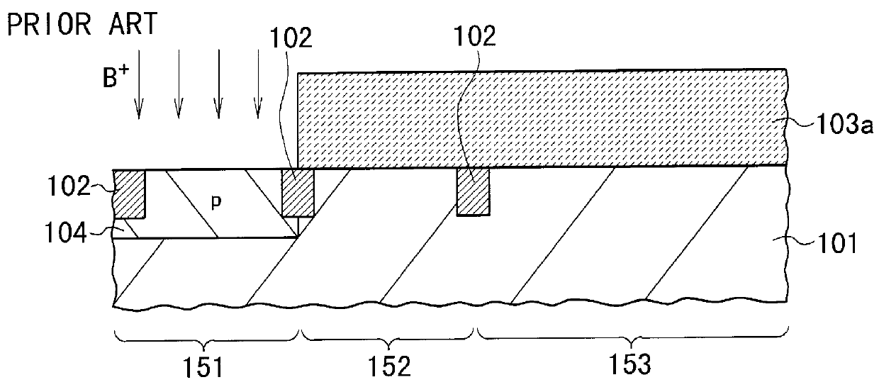
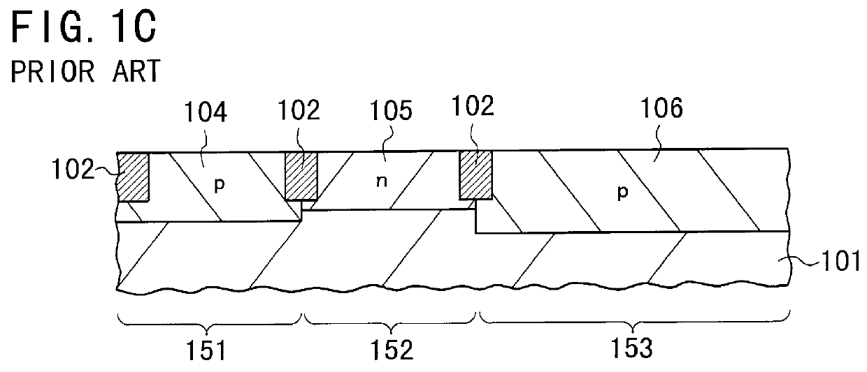
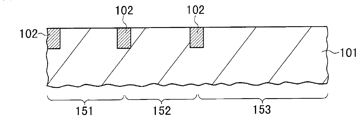
Like the conventional semiconductor memory device shown in FIGS. 1A to 1K, this memory device is comprised of a lot of nonvolatile memory cells formed by n-channel MOSFETs with floating gates and a peripheral circuitry formed by n- and p-channel MOSFETs with the CMOS structure. The peripheral circuitry serves to provide control operations for the memory cells, such as the reading operation and the writing or reprogramming operation. The memory cells are arranged in a matrix array in a memory cell area. The n-and p-channel MOSFETs of the peripheral circuitry are arranged in peripheral NMOS and PMOS areas, respectively.

In FIGS. 2A to 2K, however, two adjoining ones of the n-channel MOSFETs in the memory cells, one of the n-channel MOSFETs in the peripheral circuitry, an...

second embodiment

A flush nonvolatile semiconductor memory device, which is termed a flush EEPROM, according to a second embodiment of the present invention is fabricated in the process steps shown in FIGS. 3A to 3K.

The process steps shown in FIG. 3A to FIG. 3F are the same as those in the second embodiment shown in FIG. 2A to FIG. 2F. Therefore, the explanation about the steps in FIG. 3A to FIG. 3F is omitted here by attaching the same reference numerals to the same elements in FIGS. 3A to 3F for the sake of simplification of description.

Subsequently, as shown in FIG. 3G, a Ti film 16 with a thickness of approximately 20 nm is formed over the whole surface of the substrate 1 by a sputtering process. The, a titanium nitride (TiN) film 78 with a thickness of approximately 20 nm is formed over the whole surface of the Ti film 16 by a reactive sputtering process.

As seen from this explanation, unlike the first embodiment, the combination of the Ti and TiN films 16 and 78 is used as a refractory metal fil...


PUM


Abstract

A semiconductor device is provided, which makes it possible to decrease the electric sheet resistance of source/drain regions of MOSFETs in a peripheral circuitry without degradation of the data writing speed in nonvolatile memory cells. This device is comprised of nonvolatile memory cells and a peripheral circuitry provided on a same semiconductor substrate. The nonvolatile memory cells are formed by a first plurality of MOSFETs of a first conductivity type. The peripheral circuitry includes a second plurality of MOSFETs of the first conductivity type. Each of the first plurality of MOSFETs is equipped with a gate electrode having a floating gate for data storing and source/drain regions having substantially no silicide films. Each of the second plurality of MOSFETs is equipped with source/drain regions having silicide films and a doping concentration lower than that of the source/drain regions of each of the first plurality of MOSFETs. It is preferred that the doping concentration of the source/drain regions of the first plurality of MOSFETs is equal to 1x10¹⁹ atoms/cm3 or higher and the doping concentration of the source/drain regions of the second plurality of MOSFETs is lower than 1x10¹⁹ atoms/cm3.

Description

1. Field of the InventionThe present invention relates to a semiconductor device with a self-aligned silicide (SALICIDE) structure and a fabrication method thereof and more particularly, to a semiconductor device equipped with nonvolatile memory cells formed by Metal-Oxide-Semiconductor Field-Effect Transistors (MOSFETs) and a peripheral circuitry including MOSFETs on a semiconductor substrate, in which the MOSFETs of the peripheral circuitry have silicide layers at their source / drain regions while the MOSFETs of the memory cells have no silicide layers at their source / drain regions, and a fabrication method of the semiconductor device.2. Description of the Prior ArtConventionally, the miniaturization and integration of semiconductor elements and components have been progressing perpetually in semiconductor integrated circuit devices.In recent years, highly-integrated semiconductor integrated circuit devices (i.e., LSIs) designed according to the design rule as small as 0.15 to 0.25...

Claims


Application Information

Patent Timeline
Patent Type & Authority Patents(United States)
IPC IPC(8): H01L21/70H01L21/8247H01L27/105H01L21/28H01L27/10H01L27/115H01L29/788H01L29/792
CPCH01L27/11526H01L27/11543H01L27/11546H01L27/105H10B41/48H10B41/49H10B41/40H01L27/10
Inventor MATSUBARA, YOSHIHISAKAWATA, MASATO
Owner NEC ELECTRONICS CORP
Why Eureka
Try Eureka