Microwave heating apparatus and microwave heating method

Inactive Publication Date: 2000-03-21
PANASONIC CORP
View PDF11 Cites 87 Cited by
  • Summary
  • Abstract
  • Description
  • Claims
  • Application Information

AI Technical Summary

Benefits of technology

According to the first constitution, the invention can heat the object put in the heating chamber while emitting microwaves in the superheated steam, and can heat the object efficiently from inside and outside without moistening the surface. Depending on the type of the object of heating, either the superheated steam or the saturated vapor is changed over and used, or the superheated steam and the vapor under saturation temperature are changed over and used during heating, so that optimum heating suited to the object of heating can be done efficiently. In addition, by using the superheated steam at least in a certain period during heating, the object of heating can be dried intentionally.
According to the second constitution of the invention, the superheated steam can be generated easily.
According to the third constitution of the invention, the superheated steam is maintained in its state so that the superheated steam supplied in the heating chamber may not be lowered below the saturation temperature. Moreover, a partition wall made of porous body such as ceramic or containing fibers such as paper or cloth capable of absorbing part of superheated steam prevents dew condensation of the steam on the wall surface, and absorbed moisture is re-evaporated by microwaves, thereby preventing lowering of steam volume and temperature in the heating chamber. Or the partition wall composed of a water repellent dielectric material does not absorb superheated steam, but absorbs microwaves to raise temperature, so that the hot plate effect is exhibited to prevent lowering of temperature of the super

Problems solved by technology

Such steam damps the food surface.
In particular, when the food is frozen, an extreme dew condensation occurs on the food surface in unthawed state.
Accordingly, when froze

Method used


Image

  • Microwave heating apparatus and microwave heating method
  • Microwave heating apparatus and microwave heating method
  • Microwave heating apparatus and microwave heating method

Examples


Example

A first embodiment of the invention is described below while referring to the drawings.

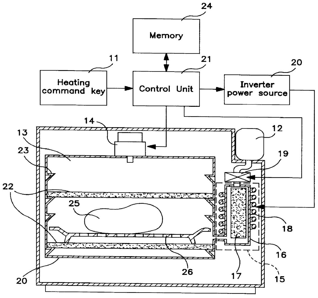
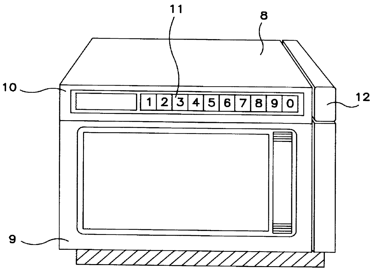
FIG. 2 is an appearance view of a microwave heating apparatus according to the invention. A door body 9 is supported at the front side of a main body 8 for closing the opening of the heating chamber in which the food is contained. A heating command key 11 is disposed on an operation panel 10, and codes entered in one digit or several digits correspond to the factors having effects on the heating method, such as the type or amount of food, storing temperature (frozen or chilled), heating end temperature and others, and they are commanded to the control unit described later. At the right side of the main body, a feed water tank 12 is detachably disposed.

FIG. 1 is a front sectional view of a heating chamber showing a first embodiment of the invention, in which a heating chamber 13 is coupled with a magnetron 14 as microwave generating means for emitting microwaves, and a steam generator 15 for genera...

Example

(Embodiment 2)

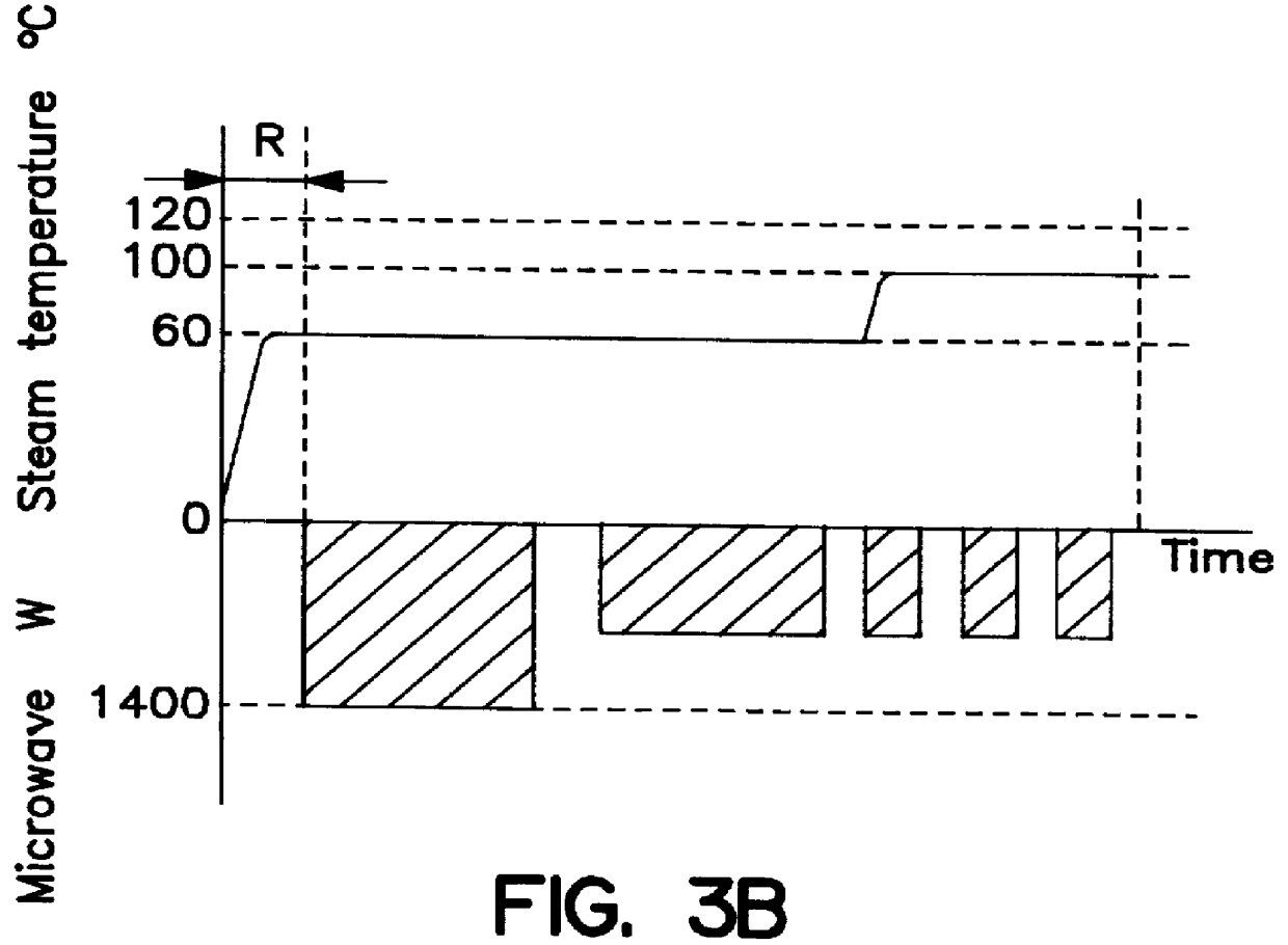
In (b) is shown an example of changing the steam temperature while heating in the heating chamber, and the first half is a medium moisture state at around 60.degree. C. and the second half is rapidly changed to superheated steam of 120.degree. C. At the same time, the microwave is decreased gradually. It was particularly effective in heating of food desired to finish with a crisp surface, such as frozen bread and fried food. That is, while preventing drying of food with a thin steam below the saturation temperature in the first half, uneven heating by microwave is slightly lessened, and the surface is dried at once by the superheated steam in the second half.

The steam temperature in the second half can be optimally selected according to the food. Favorable results were obtained at around 60.degree. C. in the frozen bread, and slightly higher around 80.degree. C. in the fried food. To warm steamed food such as dumpling and meat pie, favorable results were obtained by ab...

Example

(Embodiment 3)

FIG. 4 is a front sectional view of a heating chamber showing a different embodiment, in which the magnetron 14 is disposed at both ceiling and bottom of the heating chamber. This top-bottom power feeding is a practical technology widely employed in professional microwave oven, and a high output is obtained while maintaining a favorable electric field distribution. The object to be heated 25 is put directly on the bottom heating partition wall 22, not on the tray. Penetration holes 27 are formed in the bottom heating partition wall, and the superheated steam from the steam generator 15 is discharged to the bottom of the heating chamber 13.

In such constitution, the bottom heating partition wall 22 absorbs microwaves to rise in temperature, and the heat is directly transmitted to the object, so that the heating efficiency is excellent. Besides, the superheated steam is once discharged to the bottom of the heating chamber, when taking out the object by opening the door af...


PUM


Abstract

The invention is intended to heat a food or other object to be heated favorably by means of microwaves while enclosing the food with superheated steam. To achieve this purpose, the apparatus comprises a heating chamber in which an object to be heated is put, steam generating means for supplying superheated steam to the heating chamber, superheated steam maintaining means provided in the heating chamber to prevent the temperature of the superheated steam from lowering, and microwave generating means for irradiating the object with microwaves, whereby the object placed in the heating chamber is heated in superheated steam with microwaves, so that the food is efficiently heated from inside and outside and the food is not wetted.

Description

This application is a U.S. national phase application of PCT international application PCT / JP96 / 02868.TECHNICAL FIELD OF THE INVENTIONThe present invention relates to a heating apparatus using microwaves for heating various objects such as foods promptly while maintaining a favorable quality.BACKGROUND ARTHitherto, as a heating apparatus of this type, for example, the food thawing cooking oven as disclosed in Japanese Patent Publication No. 55-51541 has been known. FIG. 5 shows its constitution, in which an agitator 3 is provided in a ceiling 2 of an oven 1 which can be enclosed tightly, and a magnetron irradiation unit 4 is disposed nearby. A detachable food rack 5 is provided in the oven 1, a liquid pan 6 for feeding water or oil is disposed beneath, and a heater 7 by gas or electric heating is disposed further beneath. By the combination of magnetron irradiation unit 4, liquid pan 6, and heater 7, both heating by magnetron irradiation from above and steam heating by boiling water...

Claims


Application Information

Patent Timeline
IPC IPC(8): H05B6/80H05B11/00A23L3/365F24C7/02
CPCH05B6/6479F24C7/02
Inventor UEDA, SHIGEKIINADA, IKUHIROUCHIYAMA, SATOMI
Owner PANASONIC CORP
Why Eureka
Try Eureka