Apparatus for de-watering and purifying fuel oils and other liquids

a technology for fuel oils and liquids, applied in the direction of liquid displacement, separation process, filtration separation, etc., can solve the problems of storing diesel fuel or other hydrocarbon distillates such as jet fuel, kerosene, gasoline, heating oil, and fuel tank and the growth of microbial debris in the fuel tank cannot be eliminated. , the effect of reducing the number of microbial debris

Inactive Publication Date: 2000-03-28
MCAL 51
View PDF16 Cites 63 Cited by
  • Summary
  • Abstract
  • Description
  • Claims
  • Application Information

AI Technical Summary

Benefits of technology

Now referring to the drawing there is shown a water-contaminate separator in accordance with this invention. FIG. 1 illustrates a partial cross sectional and schematic view which shows a separator including an upper end plate 11 and a bottom end plate 12. An outer tubular body 10 is held between the upper and lower plates by use of a plurality of equally spaced tie rods 21 which are provided with tightening nuts 36. The tubular body is provided with back-up ring seals 38 which prevent any leakage between the ends of the tubular body and the upper and lower end plates 11 and 12. An axially aligned tube 13 extends from the bottom plate to the upper plate and is confined by a cylindrical portion of the upper and lower plates and which surround an inlet opening 49 and an outlet opening 26 in the lower and upper plates. The tube 13, FIG. 6, is provided with spaced circular grooves 56 in which spaced coalescer plates 16 and 57 are alternately held in position within the tube 13. The coalescer plates 16 and 57 are provided with center holes which surround the tube 13 and which fit in the grooves 56. The grooves 56 are formed by equal length rings 28 that fit onto the tube. Each of the coalescer plates are formed in a conical shape and placed on the tube 13 with their apex end up. The coalescer plate 16 is provided with apertures 27 as shown in FIG. 2 and the conical shape is shown in FIG. 3. The coalescer plate 57 is shown in FIG. 4 and 5, and are not provided with apertures.
The separator is shown with an air inlet valve 17, at the top, a sensor 64 at the bottom, a control box for controlling the sensors, operation, etc. The bottom plate 12 is provided with a port 48 through which contaminates pass to the sight glass tube and the sight glass tube is provided with a drain port 51 and drain valve 18. The control box contains a switch 54, a timer 55 and any other controls necessary for operating the pump, etc. A valve 19 is provided at the inlet port of the tube 13 to prevent any back flow of the fuel or water.

Problems solved by technology

Stored diesel fuel or other hydrocarbon distillates such as jet fuel, kerosene, gasoline, and heating oil will begin to degrade in storage because of microbial contamination and fungi which grow in the fuel water interface.
However, this remedy will not eliminate the growth of microbial debris within the fuel tank.
A further attempt to solve the microbial contamination problem is the use of costly and hazardous biocides to attempt to kill the micro-organisms within the tank.
This remedy however tends to clog filters with the massive influx of dead organisms.
Additionally, these filtration units have inadequate capacity to remove the volume of water and contaminates that are ingested during turbulence and rough conditions.
And further, these units only remove a small percentage of free water and very little emulsified water due to the relatively high velocity movement of fuel within the system and only operate while the engines are running.

Method used


Image

  • Apparatus for de-watering and purifying fuel oils and other liquids
  • Apparatus for de-watering and purifying fuel oils and other liquids
  • Apparatus for de-watering and purifying fuel oils and other liquids

Examples


example two

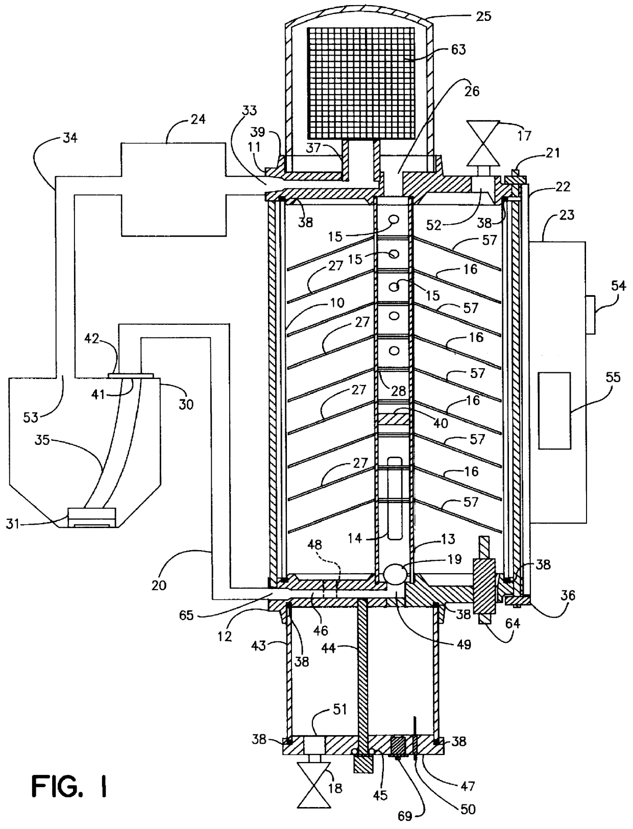
In this example, the fluid entering the vessel bottom port 65 may be 40 gallons per hour of diesel fuel No.1, with 5% water. This fluid was drawn from the bottom of a storage tank with a temperature of 80 degrees F. The pressure at opening 53 is atmospheric. The vacuum at outlet opening 33 was 3.0 inches Hg. The diesel fuel No.1 leaving outlet opening 33 has 0.00055 percent water after 7.5 minutes of operation. This single pass through of the present separator typically removed all contaminant with one single pass of the fuel.


PUM

PropertyMeasurementUnit
inner diameteraaaaaaaaaa
velocityaaaaaaaaaa
velocityaaaaaaaaaa

Abstract

An apparatus for separating water contaminants from a fuel which has a specific gravity which is lower than that of water. Contaminated fuel is drawn from a bottom of a tank and passed into a separator. The water stays at the bottom of the separator and is drained off. The fuel is forced upwardly from which any droplets of water flow along collector plates and fall to the bottom of the separator. The fuel is passed through a filter which removes any particles of matter then the fuel is directed back to the tanks. The process can be repeated for as many times as necessary to cleanse the fuel of water and contaminates.

Description

This invention relates to the removal by coalescence of water and other impurities from diesel fuel, jet fuel, gasoline, kerosene, heating oil, motor oil and other liquids with a specific gravity less than one (1).Stored diesel fuel or other hydrocarbon distillates such as jet fuel, kerosene, gasoline, and heating oil will begin to degrade in storage because of microbial contamination and fungi which grow in the fuel water interface.It is essential that the fuel used in fuel injected internal combustion engines and jet engines be free of water, algae, and other contaminates. When fuel is stored in bulk or in a vehicle, boat, and aircraft fuel tanks, water droplets condensed from the atmosphere will form inside the fuel storage tanks and their ventilation pipes and will promote the growth of microbial debris. The accumulation of this condensation and microbial growth will eventually be ingested by the engine fuel pick-up tubes which are generally located somewhat above the bottom of ...

Claims


Application Information

Patent Timeline
Patent Type & Authority Patents(United States)
IPC IPC(8): B01D17/02B67D5/58B67D7/76
CPCB01D17/0202B67D7/766B01D17/0208B01D17/0214B01D17/045Y10S210/05
Inventor LENZ, RONALD L.
Owner MCAL 51
Why Eureka
Try Eureka