Piezoelectric actuator

a technology of piezoelectric actuators and actuators, which is applied in piezoelectric/electrostrictive/magnetostrictive devices, piezoelectric/electrostriction/magnetostriction machines, electrical apparatus, etc., can solve the problems of correspondingly sensitive to breakage, the contact arrangement necessary for energizing the electrodes is rather complicated, and the overall contact arrangement and the effort involved in assembling the known piezoelectric actuators are quite complex

Inactive Publication Date: 2000-03-28
DAIMLER AG
View PDF8 Cites 21 Cited by
  • Summary
  • Abstract
  • Description
  • Claims
  • Application Information

AI Technical Summary

Benefits of technology

Also according to the invention, the actuator further comprises a support plate and contact electrodes arranged on the support plate, whereby each contact electrode has a comb-shaped configuration including contact fingers extending from a spine electrode. The contact electrodes are arranged such that the contact fingers of the opposite contact electrodes interdigitally intermesh with each other. This arrangement provides a simple structure that can be simply assembled, whereby the alternating stripe-shaped actuating electrodes are brought into contact alternately with one or the other of the contact electrodes, so as to energize the alternating actuating electrodes with an opposite polarity voltage.
By providing the stripe-shaped actuating electrodes in the form of continuous closed-loop electrodes respectively extending at least substantially entirely around the perimeter of the solid state body defined by the outer surfaces bounding the cross-section of the solid state body, the invention improves the homogeneity of the electric field pattern in the individual piezoelectric layers and thereby improves the energy efficiency of the actuator. Moreover, by providing the support plate with two interdigitally intermeshing contact electrodes arranged thereon, the invention provides a simple manner of achieving a surfacial contact between alternating ones of the stripe-shaped actuating electrodes and the alternating oppositely energized contact fingers of the two contact electrodes. Thereby the mechanical strength of the actuator assembly is increased, and the fabrication of the actuator is simplified, while achieving a secure, reliable, and problem-free electrical connection for energizing the individual actuating electrodes in the appropriate alternating manner.
In order to increase the power output capacity of the actuator in a simple manner in relation to the circuit arrangement, a further embodiment according to the invention provides for a plurality of solid state bodies arranged and secured adjacent one another on the support plate or arranged stacked on top of one another, in such a manner that the actuating electrodes of the adjacent solid state bodies mutually contact each other. In this manner, a plurality of solid state bodies can be simultaneously energized and actuated, without requiring additional complicated electrical interconnections between or among the respective actuating electrodes of the solid state bodies.
The stripe-shaped actuating electrodes are preferably sputtered onto the piezoelectric material of the solid state body in order to further simplify the fabrication of the actuator. The sputtering process may also be easily controlled to precisely achieve the desired sparing and dimensioning of the actuating electrodes without further patterning steps.

Problems solved by technology

However, in order to achieve a sufficiently homogenous electric field line pattern, the solid state body must have a rather small plate thickness and is therefore correspondingly sensitive to breakage.
Furthermore, the contact arrangement necessary for energizing the electrodes is rather complicated because a double electrode connection is necessary at the end of each piezoelectric layer.
Thus, the complexity of i-he overall contact arrangement and the effort involved in assembling the known piezoelectric actuators is quite considerable, especially if a large number of piezoelectric layers is to be used in order to achieve an advantageous amplification or summation of the piezoelectric effect.

Method used


Image

  • Piezoelectric actuator
  • Piezoelectric actuator
  • Piezoelectric actuator

Examples


Embodiment Construction

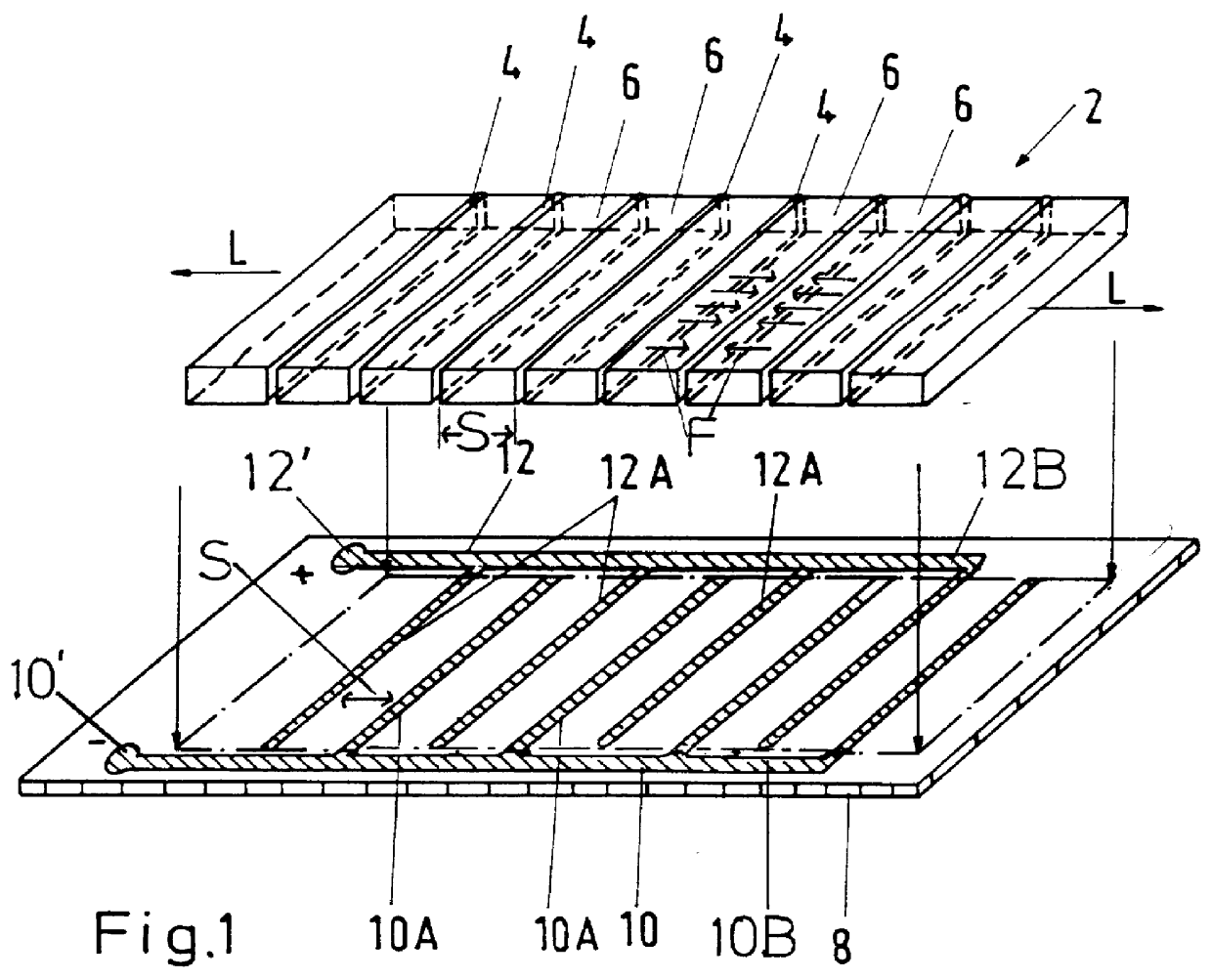
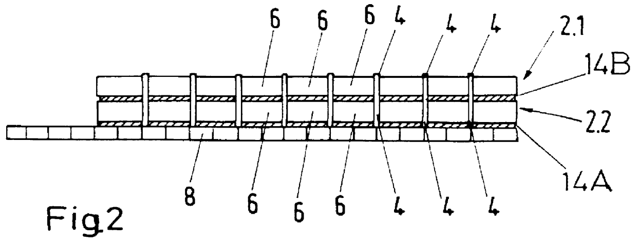
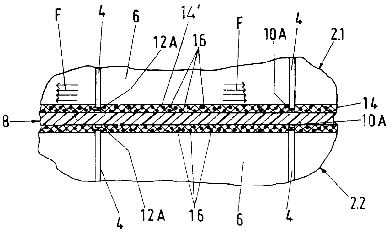
The piezoelectric actuator shown in FIG. 1 comprises a plate-shaped solid state body 2 that consists of a single integral or monolithic piece of a piezoceramic material having a lengthwise extension in a lengthwise direction L. The actuator further comprises a plurality of stripe-shaped actuating electrodes 4 that are each a respective closed loop extending substantially perpendicularly to the lengthwise direction L entirely around the perimeter of the piezoelectric solid state body 2, namely around the outer surfaces that bound the substantially rectangular cross-section of the solid state body 2. The respective adjacent electrodes 4 extend parallel to each other and are spaced apart from each other by a uniform spacing distance S in the lengthwise direction L.

If respective high and low voltage potentials, or for example positive and negative voltage potentials, are alternatingly applied to the successive actuating electrodes 4, then the differential voltage between respective adja...


PUM


Abstract

A piezoelectric actuator or sensor includes a solid state body made of a monolithic piezoelectric material, a plurality of actuating electrodes formed as closed-loop electrodes entirely around the perimeter of the solid state body, and a support plate with two contact electrodes respectively having interdigitally intermeshing contact fingers arranged thereon. The intermeshing or alternating contact fingers of the two contact electrodes respectively contact alternating ones of the actuating electrodes, preferably through an adhesive layer having conducting particles dispersed therein. The energized actuating electrodes effectively form virtual piezoelectric layers in the solid state body.

Description

This application is based on and claims the priority under 35 U.S.C. .sctn.119 of German Patent Application 197 45 468.2, filed on Oct. 15, 1997, the entire disclosure of which is incorporated herein by reference.The invention relates to a piezoelectric actuator including a solid state body of a one-piece piezoelectric material and stripe-shaped electrodes extending transversely across the surface of the solid state body, whereby alternate adjacent electrodes can be energized with opposite voltages in order to vary the length of the solid state body due to the piezoelectric effect. The solid state body includes integrally interconnected piezoelectric layers having layer thicknesses corresponding to the spacing between adjacent electrodes.BACKGROUND INFORMATIONU.S. Pat. Nos. 2,540,194 and 5,225,731 each disclose piezoelectric actuators of the above mentioned general type. Namely, the known actuators comprise a one-piece integral piezoelectric solid state body that has stripe-shaped e...

Claims


Application Information

Patent Timeline
Patent Type & Authority Patents(United States)
IPC IPC(8): H01L41/09H02N2/00H02N2/02
CPCH01L41/047H01L41/0926H10N30/87H10N30/875H10N30/204
Inventor JAENKER, PETER
Owner DAIMLER AG
Why Eureka
Try Eureka