Vapor compression type refrigerating system

a refrigerating system and vapor compression technology, applied in the field of refrigerating systems, can solve the problems of insufficient optimum control line along the co.sub.2 refrigerating system, insufficient optimum control line, and inability to achieve the desired refrigerating capacity

Inactive Publication Date: 2000-04-04
DENSO CORP +1
View PDF9 Cites 85 Cited by
  • Summary
  • Abstract
  • Description
  • Claims
  • Application Information

AI Technical Summary

Problems solved by technology

However, the CO.sub.2 refrigerating system is defective in that a pressure at the outlet of the heat emitter is increased to a value as much as 10 times of that in the conventional refrigerating system using flon when a refrigerating capacity is high due to an increased outside air temperature such as that in a summer season.
Such an increase in the pressure at the outlet of the heat emitter means that the strength of parts constructing the compressor must be correspondingly increased over those in the conventional refrigerating system using flon, resulting in an increase in the size of the system.
Thus, such control along the optimum control line does not necessarily guarantee a desired refrigerating capacity at a particular condition, such as a cool-down operation.
However, such a control may cause the degree of super-heating of the refrigerant to be insufficient at the outlet of the evaporator, which may cause a liquid state refrigerant to be sucked by the compressor, thereby damaging the compressor.
On the other hand, in a case where the degree of the opening of the pressure reducer is controlled such that a desired degree of the superheat at the outlet of the evaporator is obtained, a relationship between the pressure at the outlet of the heat emitter and the temperature at the outlet of the heat emitter deviates from the optimum control line, thereby reducing an efficiency of a refrigerating cycle using CO.sub.2.
Furthermore, the second pressure reducer allows the degree of super heating to be maintained to a predetermined value at the inlet of the compressor, thereby preventing a liquid phase of the refrigerant from being sucked to the compressor, which would otherwise cause the compressor to be damaged.
Furthermore, an introduction of a gaseous phase of the refrigerant at an intermediate pressure is introduced into the compressor, thereby reducing the compression work at the compressor.

Method used


Image

  • Vapor compression type refrigerating system
  • Vapor compression type refrigerating system
  • Vapor compression type refrigerating system

Examples


first embodiment

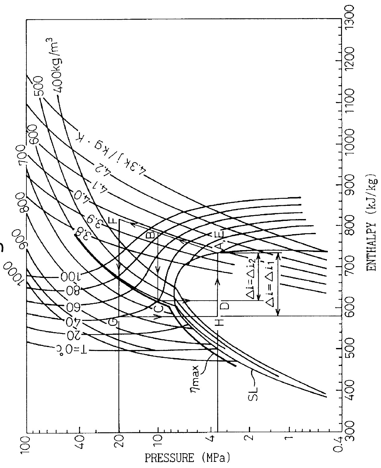
FIG. 1 is a Mollier chart illustrating an operation of the refrigerating system using CO.sub.2 as a refrigerant. In a compressor, compression of the refrigerant (CO.sub.2) of a gaseous state is done, so that a change of a state from a point A to a point B occurs. At the point B, the CO.sub.2 gas is under a condition of a high temperature and a high pressure, i.e., is in a super critical condition. The compressed refrigerant from the compressor 1 is subjected to a cooling at the heater (gas cooler), so that a state change between a point B to a point C is obtained. Thus, at the point D, the CO.sub.2 is in a gas-liquid combined state. Then, at an evaporator, the gas-liquid combined state refrigerant is subjected to an evaporation, so that a state change between the points D and A occurs. During the evaporating stage at the evaporator, a heat corresponding a latent heat of evaporation is removed from the outside air contacting the evaporator, thereby cooling the outside air. In a well ...

second embodiment

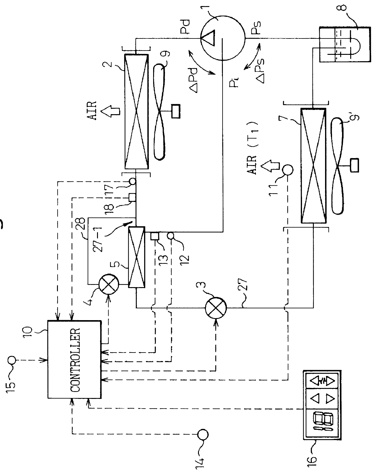
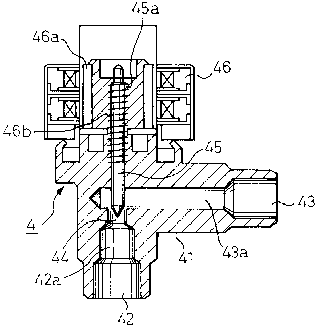
This embodiment is directed to a construction of sub-pressure reducer 4 capable of eliminating the temperature sensor 12 and the pressure sensor 13 for detecting a temperature and the pressure of the CO.sub.2 for the injection. Namely, as shown in FIG. 12, a pressure reducing device 400 is constructed by a pressure reducer unit 410, which has substantially the same construction as that of the pressure reducer 4 in the first embodiment in FIG. 2 and by a thermal expansion valve 420 which is similar construction to that used for a conventional type refrigerating system using flon. The pressure reducer 410 includes a valve member 411 located in the injection passageway 28 between the heat emitter 2 and the heat exchanger 5 as shown in FIG. 2. The thermal expansion valve 420 includes a heat sensing tube 421 located at a position suitable for detecting a temperature of CO.sub.2 at the outlet of the cooler 5 in FIG. 2. In a well known manner, a gas such as CO.sub.2 is sealingly stored in ...

third embodiment

FIG. 13 shows a third embodiment as shown in FIG. 13, which is different from the first embodiment in FIG. 2 in that, in place of the accumulator 8 in FIG. 1, a receiver 19 is arranged in the refrigerant recirculating passageway at a location downstream from the main pressure reducer 3, so that, at the receiver 19, the CO.sub.2 issued from the main pressure reducer 3 is separated to a gaseous phase and a liquid phase and in that a third pressure reducer 20 is arranged at the outlet of the receiver 19, so that a pressure of the liquid state CO.sub.2 from the receiver 19 is reduced and a mass flow amount of the CO.sub.2 is controlled in such a manner that the degree of the super heating at the inlet of the compressor 1, i.e., at the outlet of the evaporator 7, is controlled to a predetermined value.

The third pressure reducer 20 is of the same structure at that of an expansion valve used in a conventional refrigerating system using as a refrigerant flon. Namely, the third pressure redu...


PUM


Abstract

A refrigerating system, using CO2 as a refrigerant, for an air conditioner for an automobile. A pressure at the outlet of the heat emitter 2 is controlled to a target value in accordance with the temperature of the refrigerant at the outlet of the heat emitter for obtaining an operation of the refrigerating system along the optimum control line eta max. A pressure reducer 4 and a cooler 5 are provided on a branched passageway 28 branched from a refrigerant recirculating passageway 27 for injection. The cooler 5 is for obtaining a heat exchange between a flow of the refrigerant on the branched passageway 28 after being cooled by the pressure reducer and a flow of the refrigerant on the main passageway 27, thereby cooling the refrigerant directed to the evaporator. In a second aspect of the invention, a means is provided for increasing a target value of the pressure at the pressure reducer when a thermal load of the refrigerating system is high. In a third aspect, a series of pressure reducers are arranged on the main recirculating passageway. The second stage pressure reducer is controlled so as to obtain a desired value of degree of super heating at the inlet of the compressor.

Description

1. Field of the InventionThe present invention relates to a refrigerating system of a vapor compression type and is suitable for a refrigerating system where a cooling medium, such as a carbon dioxide (CO.sub.2) is used in a super critical state.2. Description of Related ArtIt has, recently, been strictly required that a refrigerant other than a fluorocarbon (flon) be used in a refrigerating system. Thus, a vapor compression type refrigerating system has been proposed in which carbon dioxide (CO.sub.2) is used as a refrigerant in order to execute a refrigerating cycle. See, for example, Japanese Examined Patent Publication (Kokoku) No. 7-18602. This type of a refrigerating system is referred to below as a CO.sub.2 refrigerating system.This CO.sub.2 refrigerating system operates, basically, in the same manner that a conventional refrigerating system, using flon as a refrigerant does. However, the CO.sub.2 refrigerating system is defective in that a pressure at the outlet of the heat ...

Claims


Application Information

Patent Timeline
Patent Type & Authority Patents(United States)
IPC IPC(8): F25B9/00F25B41/06F25B40/00
CPCF25B9/008F25B41/062F28D7/106F25B40/00Y10S62/17F25B2309/061F25B2341/063F25B2341/0653F25B2341/0662F25B2400/13F25B2600/05F25B2600/17F25B2700/1931F25B2700/1933F25B2700/2101F25B2700/2102F25B2700/2104F25B2700/2106F25B2700/21173F25B2700/21175Y02B30/72Y02B30/70F25B41/35F25B41/39F25B41/335
Inventor OZAKI, YUKIKATSUSAKAJO, YUICHISAKAKIBARA, HISAYOSHIUCHIDA, KAZUHIDE
Owner DENSO CORP
Why Eureka
Try Eureka