
Apparatus for catalytic distillation

Inactive Publication Date: 2000-04-04
THE UNIV OF ALBERTA
View PDF28 Cites 47 Cited by
  • Summary
  • Abstract
  • Description
  • Claims
  • Application Information

AI Technical Summary

Benefits of technology

It is a further object of the present invention to provide an improved catalytic distillation system providing better control over the catalytic reaction and enabling better coordination of the separation step to correspond with the reaction.
It is yet another object of the invention to provide a system wherein distribution and application of liquid to the reaction zone and separation zones is better controlled and more uniformly applied.
The main purpose of the collectors 60 is to collect the liquid in discrete pools i.e. in the sumps 62 so it may then be delivered via the pipes 22 to the inlet of next lower trough 24 immediately therebelow. It is another important purpose of the collectors to better ensure uniform distribution of the liquid over the upper surface of the tray(s) 16, 18, etc., and further to better ensure that the depth of the liquid is maintained shallow over the surface of the walls 64 and thereby improve gas liquid contact on the trays. Thus it is important that separate sumps 62 be provided in reasonably close spaced relationship i.e. position the outlets 66 between about 5 and 50 centimeters apart (2 to 20 inches) apart and thus, the adjacent top edges of adjacent sumps 60 about 2.5 to 25 centimeters (1 to 10 inches) apart.
To prevent the liquid from flowing directly into the gas passages 88 and to direct the liquid from the upper tray into the inlet 94, vapor caps 100 cover substantially the full cross sectional area of the passages 88 and preferably project slightly laterally therebeyond of the passages 88 so that the liquid from the upper dual flow tray 80 is deflected as indicated by the arrow 92A to flow into the inlets 86 and the gas from the passages 88 is deflected as indicated by the arrows 90A to flow side ways and tend to entrain the liquid represented by the arrows 92 into position over the inlets 94.
FIG. 9 show the unit essentially the same as FIG. 1 but with packing 110 interposed between adjacent troughs 24. The packing 110 improves the contact between liquid and gas as they flow currently through the packing.

Problems solved by technology

1. Cloth Belt (U.S. Pat. No. 4,215,011). The catalyst is sealed in a cloth belt. The belt is then wrapped in open mesh knitted stainless steel wire. Liquid can penetrate into and flow out from the catalyst through the cloth. The wetted surface of the cloth belt provides the vapor-liquid interfacial area for mass transfer. The mass transfer efficiency for this kind of catalyst units is very low because of the low interfacial area. The effectiveness of the catalyst inside the belt may change from location to location because of the different liquid residence time. This reduces the overall system efficiency.
2. Catalyst Container Held on a Tray (U.S. Pat. Nos. 4,536,373, 4,439,350, and 5,447,609). One type of this catalytic distillation unit consists of a normal distillation tray and a parallel array of rectangular tubes (troughs) filled with catalyst. The tubes (troughs) are constructed by metal screen and closed at both ends. The parallel tubes (troughs) may be supported above a distillation tray but should be located in froth zone when the column is in operation. The liquid flows across the tray in either parallel or right angle to the tubes (troughs).
The structure of these units is usually quite complex.
The catalyst quantity that can be loaded is limited.
It is not suitable if the catalytic reaction step is slower because the reaction rate may not be matched with mass transfer rate.
Therefore, it is not suitable to slow reaction.
The cost of the internals could be very high.
The structure of these units are really complex.
Therefore, the efficiency could be low.
In these units, the catalyst loading is limited by the downcomer size.
It is not suitable for slow reaction processes.
The liquid distribution to the beneath catalyst bed can be deteriorated if the plate is not properly installed.
All these may cause the uncertainty in the operation of such a catalytic distillation unit.
It will be apparent that each or the different types of units have their advantages and disadvantageous.
However, none the above described systems provide structures that may easily be adapted to couple a specific reaction with a desired separation i.e. for any given catalytic reaction there is a corresponding separation rate.

Method used


Image

  • Apparatus for catalytic distillation
  • Apparatus for catalytic distillation
  • Apparatus for catalytic distillation

Examples


Embodiment Construction

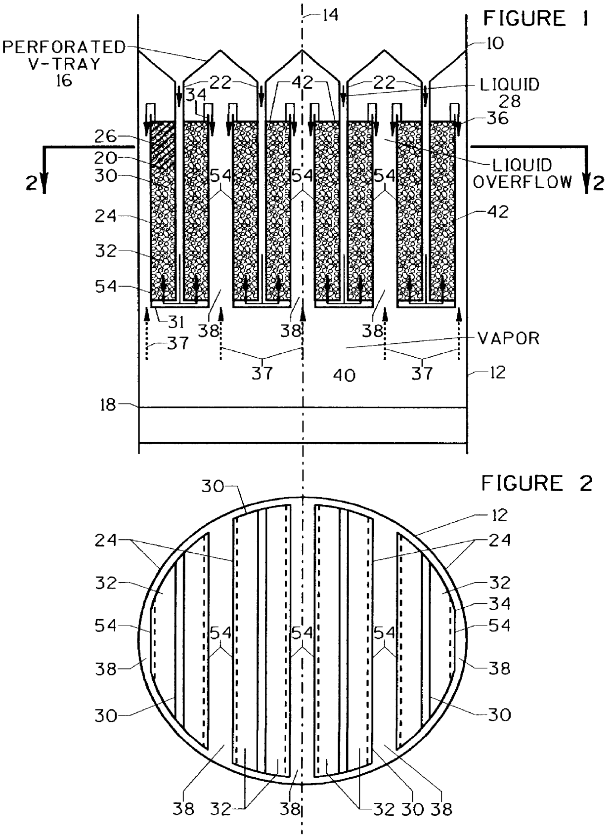
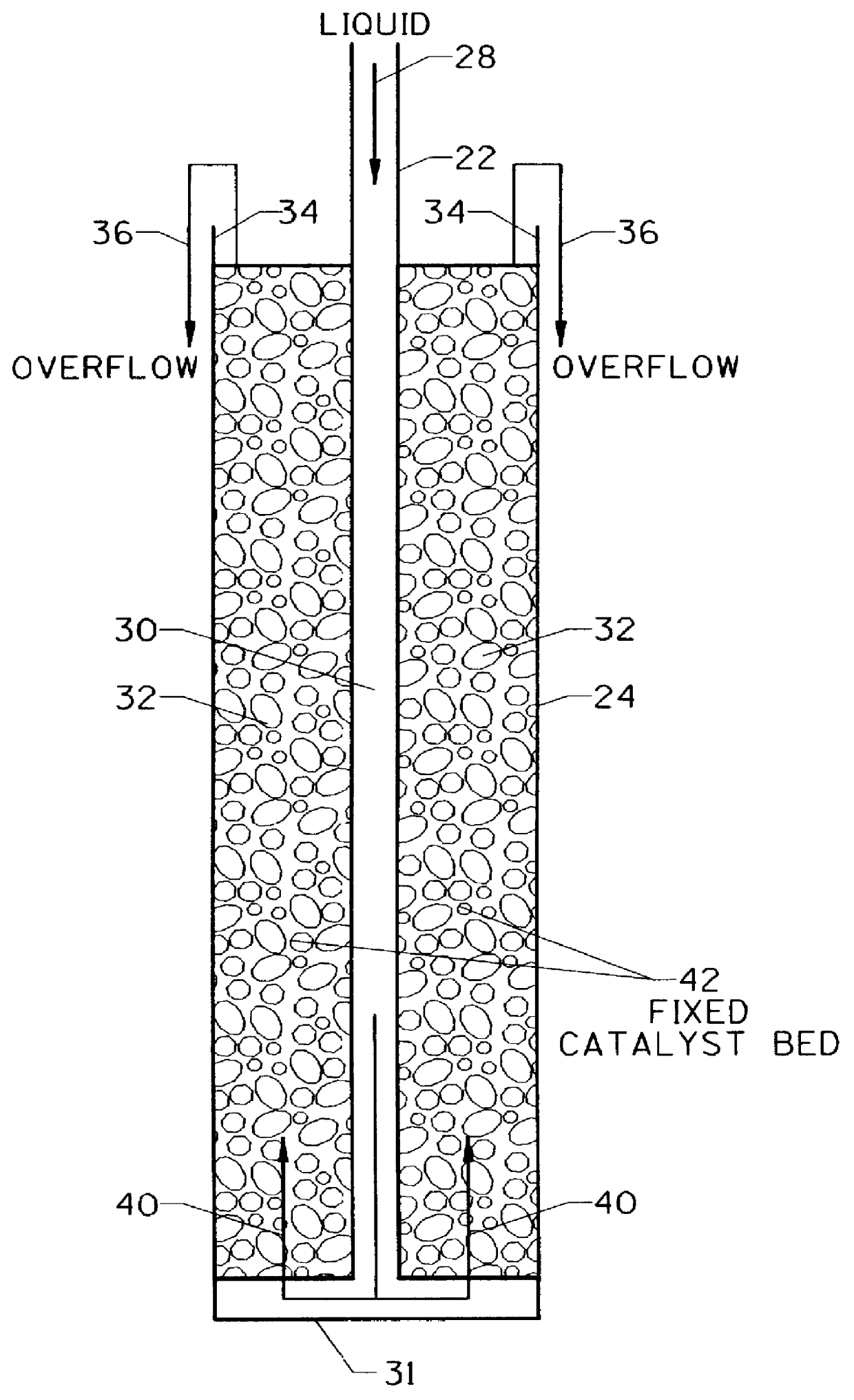
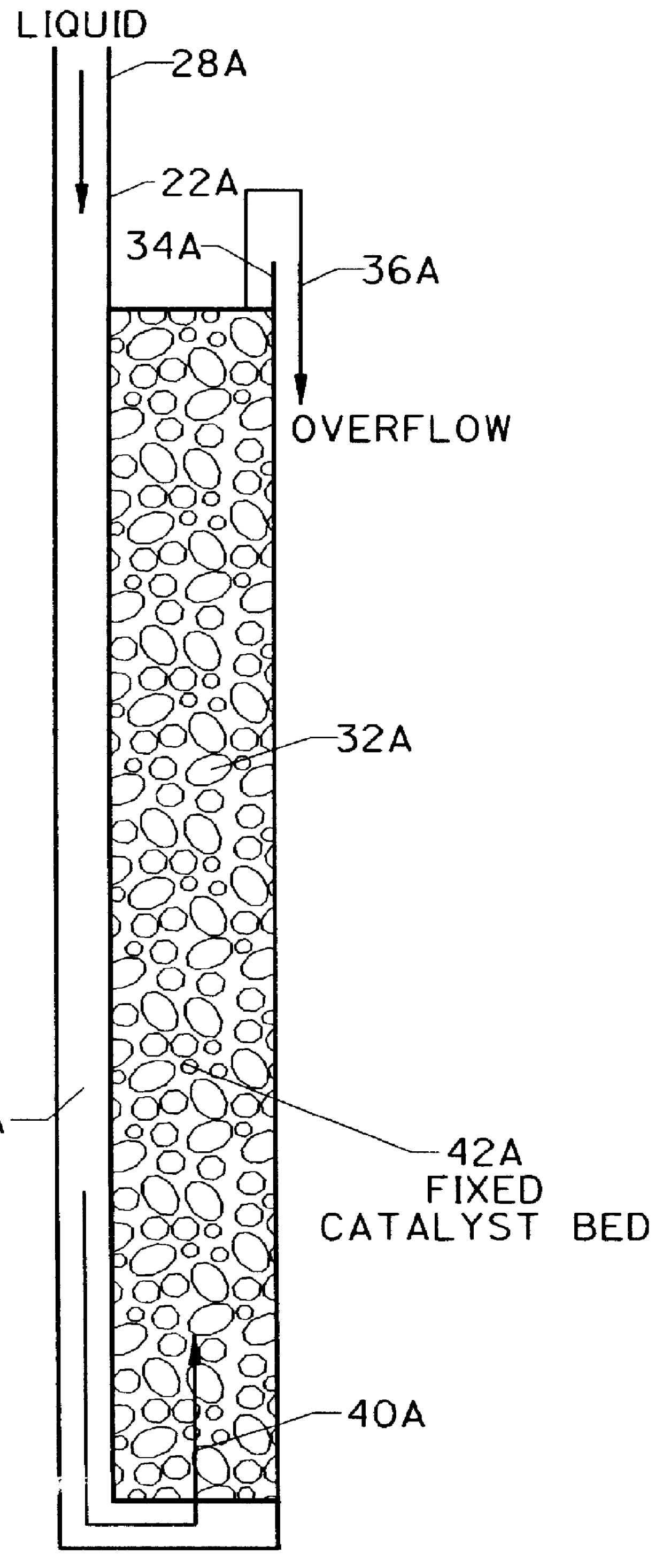
The present invention was applied in an apparatus having a flow system as indicated at FIG. 11. In this particular arrangement which is similar to that shown in FIG. 8, the column 200 has a diameter of 100 millimeters (mm.) that included seven trays and six catalyst unit. The catalyst units are constructed with two concentric troughs filled with catalyst and a vapor channel is located between the two concentric troughs. The height of each catalyst bed is 90 mm. and each trough is positioned 100 mm below the tray 16 thereabove.

Tray spacing is 220 millimeters. The perforations of the dual flow tray are 4.8 mm in diameter and are uniformly distributed over and occupy 12% of the column cross sectional area.

Methanol and a mixture of acetic acid / water containing 6% of acetic acid were fed to the column at rates of 30 grams per minute and 140 grams per minute respectively. 24 grams per minute of product was withdrawn from the column top and the rest was discharged from the column bottom. T...


PUM

PropertyMeasurementUnit
Flow rateaaaaaaaaaa
Levelaaaaaaaaaa
Mass transfer coefficientaaaaaaaaaa

Abstract

An apparatus for catalytic distillation consists of alternatively a catalyst unit and an active liquid distributor tray. The catalyst unit is formed by series of troughs containing catalysts with spaces between adjacent troughs for vapor flow. The active liquid distributor tray is preferably a V-shaped tray formed with collectors that function as both a liquid distributor to deliver liquid at the appropriate locations to the underneath catalyst unit and a mass transfer device. Liquid flows down to the catalyst toughs from bottom of the sump of each collector and vapor flows up through the upper diverging walls of the collector. Packing materials may be placed on the tray or in the spaces between the troughs or both to enhance mass transfer. The catalyst troughs preferably are partitioned to cause the liquid to flow through the catalyst and to overflow the upper rim of the troughs to escape therefrom whereby the catalyst is maintained submerged.

Description

The present invention relates to an apparatus for catalytic distillation, more particularly the present invention relates to an improved contactor tray and / or reaction trough for a catalytic distillation apparatus.Catalytic distillation is an emerging technology in which two distinct operations namely the catalytic reaction and the separation are carried out in one unit. Carrying out such a combination of steps in one unit has the potential to save energy, increase reaction conversion rate, improve product quality and reduce investment and operating costs.The key part of developing the catalytic distillation technology is the design of internals for the catalytic distillation columns. The functions of column internals are to carry out both catalytic reaction and mass transfer simultaneously. In the past ten years, numerous patents have been awarded for the new design of the internals. They can be classified as follows:1. Cloth Belt (U.S. Pat. No. 4,215,011). The catalyst is sealed i...

Claims


Application Information

Patent Timeline
IPC IPC(8): B01J8/04B01D3/00B01D3/14B01D3/20B01D3/16
CPCB01D3/008B01D3/009B01J8/0492B01J8/0484B01D3/20
Inventor CHUANG, KARL TZE-TANGXU, ZHANPING
Owner THE UNIV OF ALBERTA
Learn More