Cathode ray tube apparatus

a cathode ray tube and tube technology, applied in the direction of cathode-ray/electron beam tube electrical connection, instruments, television systems, etc., can solve the problem that the above-mentioned conventional cathode ray tube apparatus has a disadvantage in cos

Inactive Publication Date: 2000-04-25
PANASONIC CORP
View PDF4 Cites 3 Cited by
  • Summary
  • Abstract
  • Description
  • Claims
  • Application Information

AI Technical Summary

Problems solved by technology

However, the above-mentioned conventional cathode ray tube apparatus has a disadvantage in cost because of the expensive smoothing capacitor 2 having the large capacity for reducing the extraneous electric fields.

Method used


Image

  • Cathode ray tube apparatus
  • Cathode ray tube apparatus
  • Cathode ray tube apparatus

Examples


Embodiment Construction

The following is an example carried out in order to confirm the effect and advantages of the present invention.

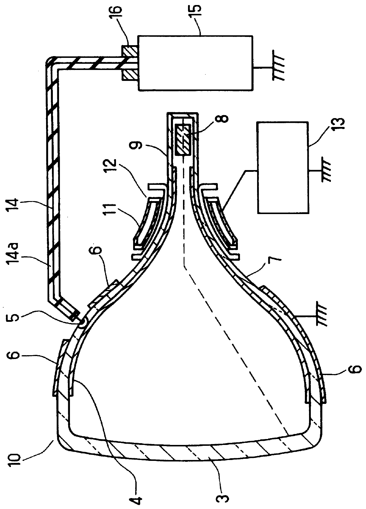
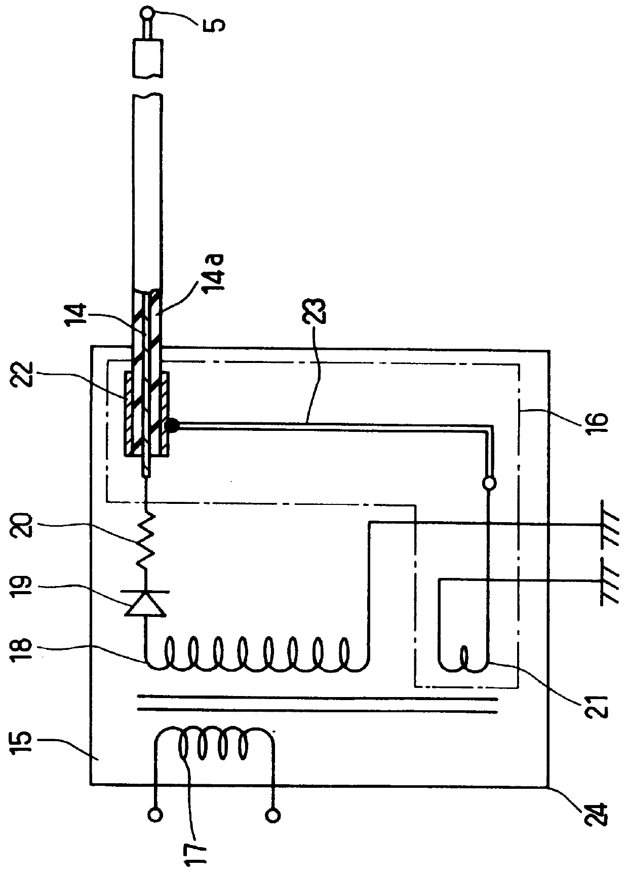
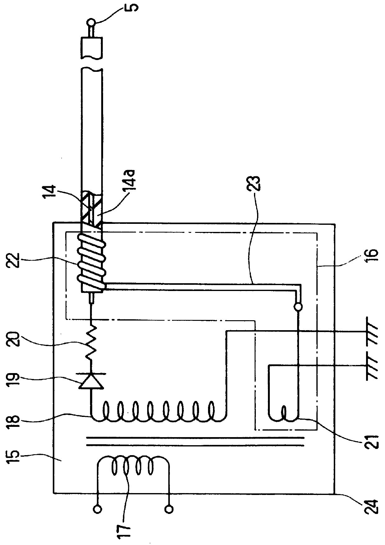
In the working example, a 17-inch size cathode ray tube shown in FIG. 1 and the flyback transformer 15 and the leakage extraneous electric field controller 16 shown in FIG. 3 were used. In the flyback transformer 15, high direct current voltage applied to the first lead wire 14 from the second coil 18 via the diode 19 and 23 was 3 turns, the pitch of turns of the spiral of the second lead wire 23 was 10 mm (about 0.4 inch), and the voltage of the negative pulse applied to the second lead wire 23 from the third coil 21 was 800 V. In order to compare with the above-mentioned working example, the conventional cathode ray tube apparatus was prepared as a reference example. The reference example comprised the same configuration as the working example without the leakage extraneous electric field controller 16.

The leakage extraneous electric fields of the front, side and rear of ...


PUM


Abstract

A cathode ray tube apparatus that can reduce the leakage extraneous electric field with low cost. The cathode ray tube apparatus comprises a front panel, a glass bulb having a funnel part including an anode terminal at the outer surface thereof and a neck part including an electron gun, a deflection apparatus comprising a horizontal deflection coil on the outer surface of the funnel part and the neck part of the glass bulb, a flyback transformer connected to the anode terminal of the funnel part via a first lead wire having an insulating coating, and a leakage extraneous electric field controller installed on the first lead wire. The controller reduces the leakage of the extraneous electric field from the first lead wire. It is preferable that the leakage extraneous electric field controller comprises a negative pulse generator generating negative pulses having a reverse polarity and a synchronized period with respect to the horizontal deflection voltage signal of the horizontal deflection coil, a conductor at least partially surrounding the insulation coated first lead wire, and a second lead wire connecting the negative pulse generator and the conductor.

Description

1. Field of the InventionThe present invention relates to a cathode ray tube apparatus used for a television display, a display monitor and so on.2. Description of the Prior ArtThe reduction of extraneous electric fields leaked from a cathode ray tube apparatus is important because the cathode ray tube apparatus generates strong electric fields. As shown in FIG. 5, in order to reduce the extraneous electric fields, a conventional cathode ray tube apparatus includes a negative pulse generator 1 that generates negative pulses having a horizontal deflection period and the generator includes a smoothing capacitor 2 whose capacity is from 3000 to 6000 (pF). The conventional cathode ray tube apparatus compensates for ripples of the high-pressure voltage HV having a horizontal deflection period by superimposing the negative pulses generated by the negative pulse generator 1 via the smoothing capacitor 2 onto the high-pressure voltage HV. Therefore, the cathode ray tube apparatus can compen...

Claims


Application Information

Patent Timeline
Patent Type & Authority Patents(United States)
IPC IPC(8): H01J29/00G09G1/00H01J29/92H01J29/90H04N5/68H04N9/29
CPCH01J29/003H01J2229/0015H04N9/29
Inventor OSHIMA, YOSHIFUMIARIMOTO, NOZOMUSUZUKI, ATSUSHI
Owner PANASONIC CORP
Why Eureka
Try Eureka