Trench capacitor structures

Inactive Publication Date: 2000-05-02
IBM CORP
View PDF5 Cites 39 Cited by
  • Summary
  • Abstract
  • Description
  • Claims
  • Application Information

AI Technical Summary

Problems solved by technology

Present trench decoupling capacitors suffer, however from long resistor-capacitor (RC) delays (in the range of nanoseconds (ns)).
Dense static random access memory (SRAM) cells resulting from advances in lithography and other technology enhancements are reaching the point where the amount of

Method used


Image

  • Trench capacitor structures
  • Trench capacitor structures
  • Trench capacitor structures

Examples


Embodiment Construction

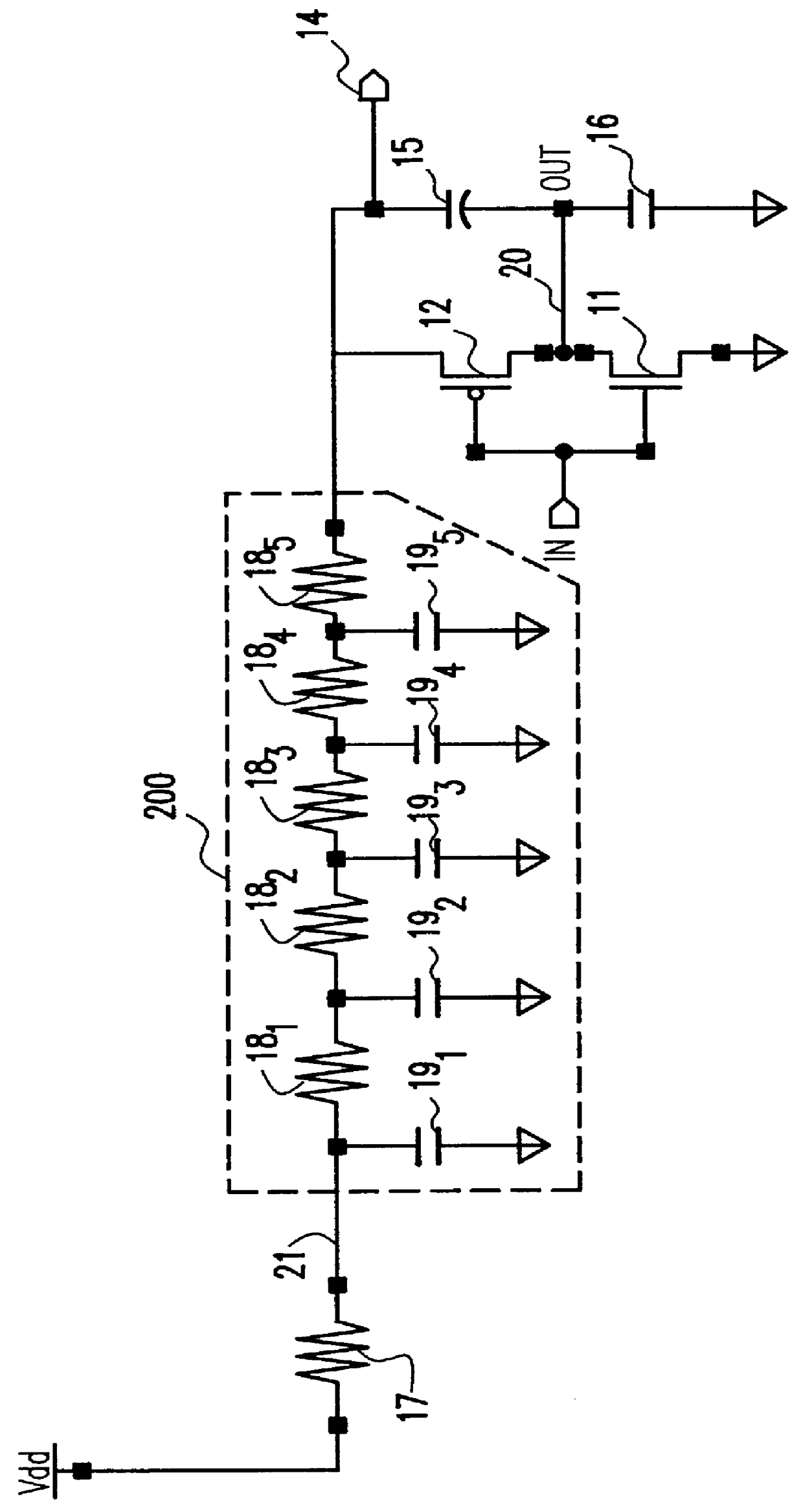
Referring now to the drawings, and more particularly to FIG. 1, there is shown an electrical model of a decoupling capacitor and an inverter circuit implemented in complementary metal oxide semiconductor (CMOS) technology. This combination of inverter circuit, consisting of an n-channel transistor 11 and a p-channel transistor 12, and decoupling capacitor 200 makes it possible to determine the drop in power supply voltage as the inverter switches for various decoupling capacitor time constants.

The decoupling capacitor 200 consists of capacitor segments 19.sub.1 to 19.sub.5 and resistor segments 18.sub.1 to 18.sub.5 in order. The combination of resistor and capacitor values determines the time constant of the decoupling capacitor. To show the effect of the time constant of the decoupling capacitor on the drop in power supply voltage for a fixed value of decoupling capacitance, only the resistor segments 18.sub.1 to 18.sub.5 are varied. Before the inverter switches, the decoupling cap...


PUM


Abstract

An optimized trench capacitor structure which is useful as a decoupling capacitor or a storage capacitor can be manufactured without added process complexity. As an on-chip decoupling trench capacitor structure, the structure reduces the series resistance to outer and inner plates and results in an acceptable RC delay, while maintaining a high capacitance per unit area. As a storage capacitor with a buried shield, the trench capacitor structure exhibits high immunity to alpha particle and cosmic radiation induced failures. The trench capacitor structure which includes a buried n-well in a silicon substrate. A trench is formed in the substrate and extends through the buried n-well. A dielectric film is formed on an inner surface of the trench, and an inner plate formed as a polysilicon fill within the trench is connected to a surface n+ film formed during definition of peripheral source/drain contacts of the integrated circuit. An outer plate of the capacitor in the form of an out diffusion from the trench provides a low resistance electrical contact with the substrate. A number of these capacitors can be combined in a very efficient X-Y array of decoupling capacitors.

Description

1. Field of the InventionThe present invention generally relates to on-chip trench capacitor structures and, more particularly, to trench capacitor structures which optimize capacitors for diverse applications without added process complexity. The trench capacitor structures have particular application as decoupling capacitors and as node capacitors that enhance the soft-error immunity in, for example, static random access memory (SRAM) cells.2. Background DescriptionOne of the attributes of a decoupling capacitor is that it should exhibit a time response comparable to that of typical circuits, ranging from 250-300 picoseconds (ps). Present trench decoupling capacitors suffer, however from long resistor-capacitor (RC) delays (in the range of nanoseconds (ns)). Thus, there is a need for a decoupling capacitor structure which has a high capacitance per unit area yet has a time constant comparable to typical circuit switching time constants.Dense static random access memory (SRAM) cell...

Claims


Application Information

Patent Timeline
IPC IPC(8): H01L27/11H01L27/108H01L29/94
CPCH01L27/10829H01L29/945H01L27/1104Y10S257/903H10B12/37H10B10/12H01L27/04
Inventor EL-KAREH, BADIHKLEINHENZ, RICHARD LEOSCHUSTER, STANLEY EVERETT
Owner IBM CORP
Why Eureka
Try Eureka