Plasma generating apparatus and ion source using the same

a technology of generating apparatus and ion source, which is applied in the field of generating apparatus, can solve the problems of large size of the apparatus as a whole, difficult to dispose of such large electrons, and disadvantages of conventional ion sources

Inactive Publication Date: 2000-05-09
NISSIN ELECTRIC CO LTD
View PDF3 Cites 47 Cited by
  • Summary
  • Abstract
  • Description
  • Claims
  • Application Information

AI Technical Summary

Problems solved by technology

The ion source described above has a drawback that this apparatus as a whole necessarily has a large size because it has the electron-generating chamber 100 separately from the plasma-generating chamber 112.
The conventional ion source has another drawback as follows.
However, it is difficult to dispose such large electron-generating chambers 100 for one plasma-generating chamber 112 while preventing the electron-generating chambers 100 from interfering with each other mechanically or magnetically.
Consequently, the formation of a plasma or ion beams over a large area is difficult.
In addition, the cylindrical coil 106 necessitates a direct-voltage source for exciting the same, and this results not only in a further increase in the size of the whole apparatus but in an increased cost.

Method used


Image

  • Plasma generating apparatus and ion source using the same
  • Plasma generating apparatus and ion source using the same
  • Plasma generating apparatus and ion source using the same

Examples


Embodiment Construction

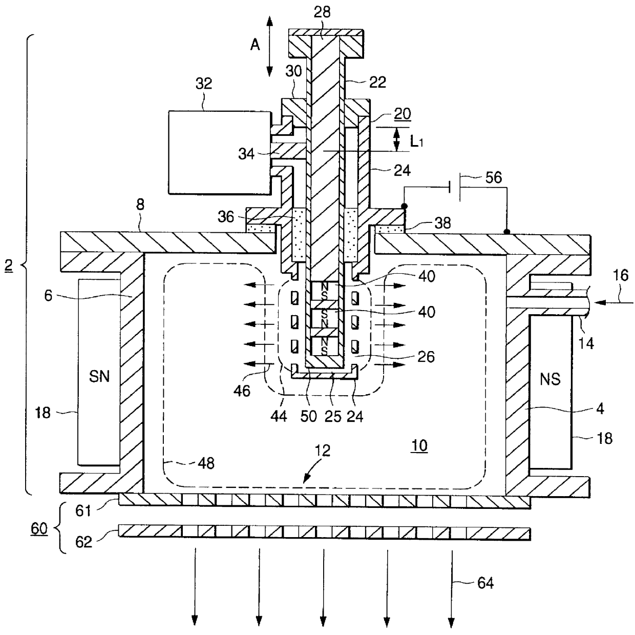
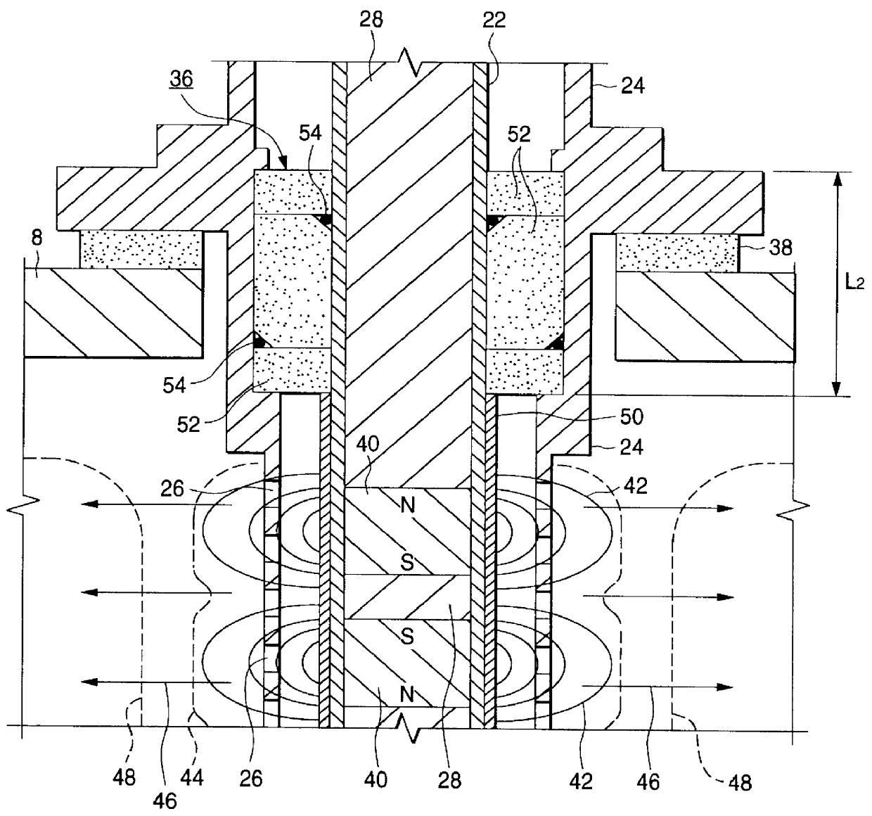
FIG. 1 is a sectional view illustrating one embodiment of the ion source using a plasma generating apparatus according to the present invention. FIG. 2 is an enlarged sectional view of the ion source shown in FIG. 1 which view illustrates some of the permanent magnets and nearby components.

This ion source has a structure including: a plasma generating apparatus 2 containing a plasma-generating vessel 4 having an opening 12; and an extracting electrode 60 disposed close to the opening 12. The extracting electrode 60 serves to extract ion beams 64, by the action of an electric field, from a main plasma 48 formed within the plasma-generating vessel 4.

The extracting electrode 60 in this embodiment consists of two porous electrodes, i.e., a first electrode 61 and a second electrode 62. However, the extracting electrode 60 may be constituted of one electrode or three or more electrodes. In place of the pores, one or more holes or slits may be formed in each constituent electrode.

The plasm...


PUM

PropertyMeasurementUnit
direct-current voltageaaaaaaaaaa
outer diameteraaaaaaaaaa
widthaaaaaaaaaa

Abstract

A plasma generating apparatus has a plasma-generating vessel into which a gas is introduced. A coaxial line is inserted into the plasma-generating vessel. The coaxial line is insulated from the vessel with an insulator. The coaxial line has a central conductor and an outer conductor, to both of which microwave is supplied from a magnetron. That part of the central conductor which is located inside the plasma-generating vessel has, disposed therein, permanent magnets which form a cusp field. A seed plasma is formed around the permanent magnets by microwave discharge. A direct-current voltage is applied from a direct-voltage source between the outer conductor 24 and the plasma-generating vessel. Upon this application, electrons in the seed plasma move toward the inner wall of the plasma-generating vessel and are accelerated to ionize the gas. The ionized gas serves as seeds to cause arc discharge between the outer conductor and the plasma-generating vessel to generate a main plasma. By disposing an extracting electrode at the opening of the plasma-generating vessel, ion beams can be extracted from the main plasma.

Description

1. Field of the InventionThe present invention relates to a plasma generating apparatus in which a seed plasma is generated by high-frequency discharge and electrons in the seed plasma are used to generate a main plasma by direct-current discharge. This invention further relates to an ion source in which ion beams are extracted from the main plasma generated by the plasma generating apparatus.Besides being used for an ion source, such a plasma generating apparatus can be utilized as the plasma generating apparatus of a plasma-assisted CVD apparatus, plasma-etching apparatus, etc. The ion source using such a plasma generating apparatus can be utilized, for example, in an ion-doping apparatus (non-mass-separation type ion implanter) for producing liquid crystal display and in an ion-beam apparatus, e.g., an ion implanter for ion implantation into semiconductor substrates, etc.2. Description of the Related ArtAn ion source having an electron-generating chamber and a plasma generating c...

Claims


Application Information

Patent Timeline
Patent Type & Authority Patents(United States)
IPC IPC(8): H01J27/16H01J27/18H05H1/46C23C14/46C23C16/50C23C16/511C23F4/00H01J37/08H01L21/205H01L21/265
CPCH01J27/18H05H1/46H01J2237/0817
Inventor MAENO, SHUICHIANDO, YASUNORIMATSUDA, YASUHIRO
Owner NISSIN ELECTRIC CO LTD
Why Eureka
Try Eureka