Switching power supply device

a power supply device and power supply technology, applied in the direction of electric variable regulation, process and machine control, instruments, etc., can solve the problems of large switching loss, emi (electromagnetic interference) noise, interference with electronic equipment,

Inactive Publication Date: 2000-05-09
MURATA MFG CO LTD
View PDF9 Cites 87 Cited by
  • Summary
  • Abstract
  • Description
  • Claims
  • Application Information

AI Technical Summary

Problems solved by technology

(1) The switching frequency is significantly varied in dependence on an output current. This causes problems such as interference with electronic apparatus and generation of EMI (electromagnetic interference) noises.
(2) The switching loss is large (the switching loss is defined as a product of Vds1 and id1 obtained at turn-on or turn-off of Q1 in FIG. 27).
(3) The energy loss is large, influenced by the leakage inductance of the transformer.
(4) Voltage surge is caused when the switching element is off, as shown in FIG. 27. Accordingly, it is required for the switching element to have a high breakdown voltage.
(5) A voltage surge is caused when the rectifying diode in the secondary is off. Thus, it is necessary that the rectifying diode have high breakdown voltage.
(6) A large reverse recovery loss is caused by the rectifying diode in the secondary circuit.
(7) The EMI noise is large, caused by the switching surge of the switching element and the rectifying diod

Method used


Image

  • Switching power supply device
  • Switching power supply device
  • Switching power supply device

Examples


first embodiment

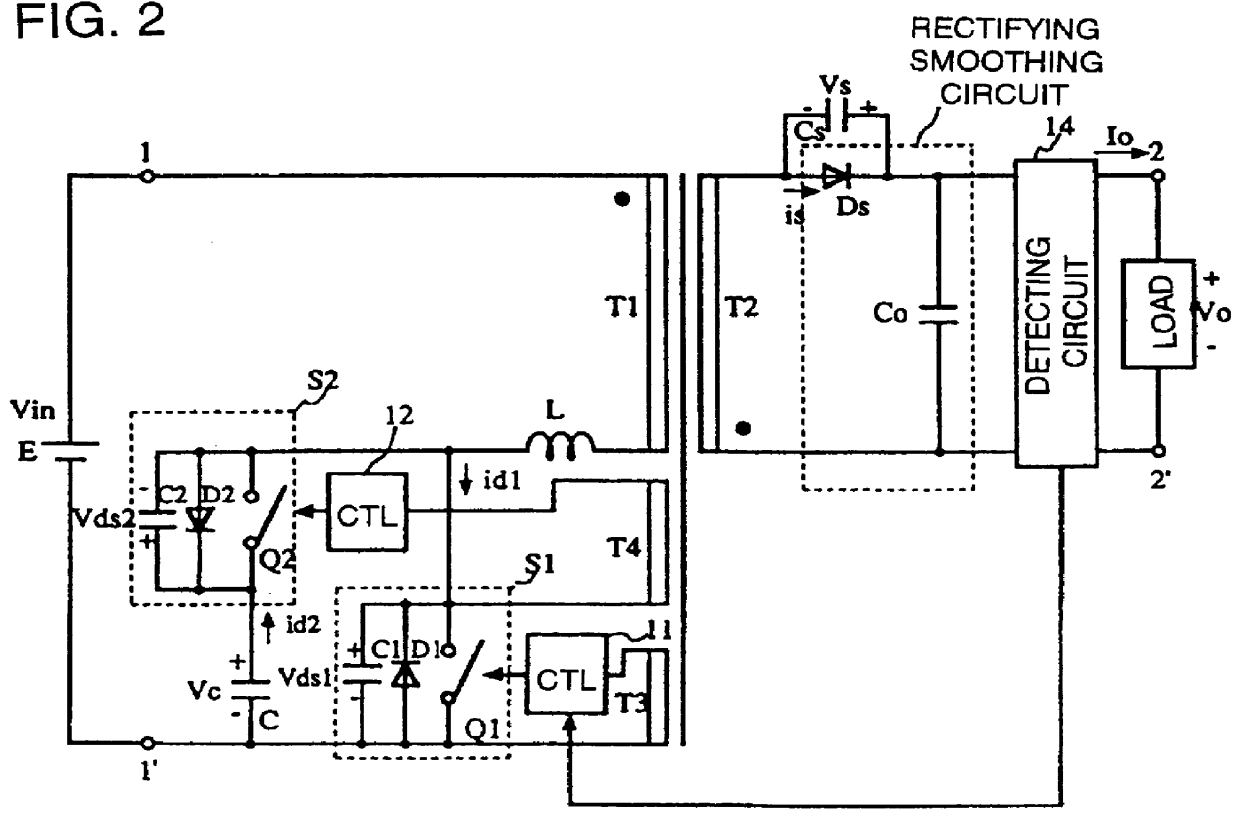
FIG.1 is a diagram showing the configuration of a switching power supply circuit according to the present invention. In FIG. 1, a transformer is designated by T. The series combination of a first switching circuit S1 and an input power supply E is connected series with the series combination of the primary winding T1 and an inductor L. The series combination of a second switching circuit S2 and a capacitor C is connected in parallel to the series combination of the primary winding T1 and the inductor L. The secondary winding T2 of the transformer T is provided with a rectifying smoothing circuit made up of a rectifying diode Ds and a smoothing capacitor Co.

In FIG. 1, the first switching circuit S1 is formed of a parallel connection circuit including a first switching element Q1, a first diode D1, and a first capacitor C1. The second switching circuit S2 is formed of a parallel connection circuit including a second switching element Q2, a second diode D2, and a second capacitor C2 co...

second embodiment

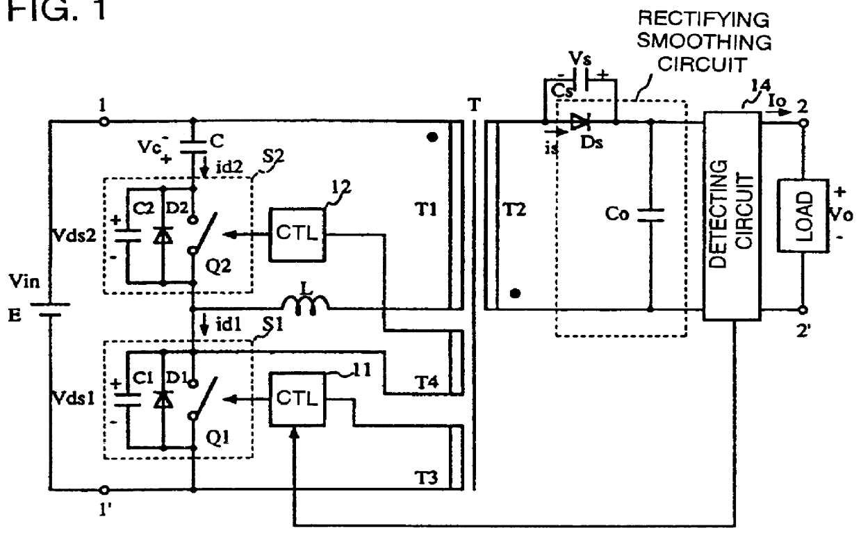
FIG. 2 is a diagram showing the configuration of a switching power supply circuit according to the present invention. In this figure, the series combination of the second switching circuit S2 and the capacitor C is connected in series with the primary winding T1 of the transformer, the inductor L, and the input power source E. As is evident in comparison with the circuit of FIG. 1, this circuit has a configuration in which the input power source E is further connected in series with the series combination of the primary winding T1 of the transformer, the second switching circuit S2, and the capacitor C, and the current id 2 is permitted to flow in the second switching circuit through the input power source. Other operation of this circuit is similar to that as described wit reference with FIG. 1.

third embodiment

FIG. 3 is a diagram showing the configuration of a switching circuit according to the present invention. In the configuration of the switching power supply circuit, the bias winding T3 of the transformer T is used as a common element, and the controlling circuits 11, 12 control the switching elements Q1, Q2, respectively. More particularly, by inputting a voltage produced in the bias winding T3, and which is substantially proportional to a voltage in the primary winding T1, the controlling circuits 11, 12 control, for example, turning Q1 on when the voltage is positive, and turning Q2 on when the voltage produced in the bias winding T3 is negative. Thus, Q1, Q2 are turned on and off alternately, by self-oscillation, carrying out the operation as illustrated in FIG. 24. In this circuit, there is no state that both Q1, Q2 are on. Q1, Q2 are turned on and off alternately, automatically. Accordingly, the configurations of the controlling circuits 11, 12 can be simplified. Moreover, a tr...


PUM


Abstract

A switching power supply device has a configuration in which a series combination of a first switching circuit and an input power source is connected in series with a series combination of a primary winding of a transformer and an inductor, a series combination of a second switching circuit and a capacitor is connected in parallel to the series combination of the primary winding of the transformer and the inductor, and the secondary winding of the transformer is provided with a rectifying smoothing circuit including a rectifying element. The first switching circuit is made up of a parallel connection circuit including a first switching element, a first diode, and a first capacitor. The second switching circuit is made up of a parallel connection circuit including a second switching element, a second diode, and a second capacitor. A switching controlling circuit is provided adapted to turn the first and second switching elements on and off alternately, with a period of time when both switching elements are off is interposed, and a capacitor is connected in parallel to the rectifying diode in the rectifying smoothing circuit.

Description

1. Field of the InventionThe present invention relates to a switching power supply device for providing a regulated direct current (DC) power supply.2. Description of the Related ArtWith the miniaturization of electronic equipment, it has been more required for switching power supply devices incorporated in electronic apparatus to have a reduced loss, that is, an enhanced efficiency.Conventionally, as a switching power supply device which can be constructed with a reduced number of the components at a relatively low cost, an RCC (ringing choke converter) as stated in Japanese Unexamined Utility Model Publication No. 63-100993 has been used.FIG. 26 is a diagram showing an example of a conventional RCC switching power supply device. In FIG. 26, a transformer is designated by T. A switching element Q1 and an input power source E are connected in series with a primary winding T1 of the transformer T. A secondary winding T2 of the transformer T is provided with a rectifying smoothing cir...

Claims


Application Information

Patent Timeline
IPC IPC(8): H02M3/335H02M3/24H02M3/338H02M3/28
CPCH02M3/3385H02M3/33569H02M3/33571H02M3/01
Inventor HOSOTANI, TATSUYA
Owner MURATA MFG CO LTD
Why Eureka
Try Eureka